Module 3: Sequential Circuit Design
Circuits that remember
Ask a combinational circuit what its last input was and it cannot tell you. Its output is a function of the inputs it has right now, and nothing else. Give it the same inputs twice and you get the same output twice.
Now try to build a toggle switch with one: press the button and the light comes on, press it again and it goes off. There is no answer from the current input alone. The output depends on how many times the button has been pressed before, and no Boolean expression of the present inputs can capture that. The circuit has to remember something.
The moment a circuit has to remember anything, a previous press, a running count, which step of a protocol it is on, which instruction ran last, you are in sequential logic, and that is Module 3.
Memory is what makes a computer
A calculator is combinational at heart: two numbers and an operation in, a result out, no history. A computer is different in kind. It runs a program, and every step depends on what happened in the steps before. It has registers holding values, a program counter saying where it is, a stack recording where it has been. All of that is state, information that persists and shapes what happens next.
The unit of state is the flip-flop, a circuit that holds one bit until told to change it. Every register file, every cache line, every pipeline register and every FIFO is flip-flops repeated. Understand the flip-flop and you understand the memory hierarchy from the bottom.
The shape of a sequential circuit
A sequential circuit has two parts (Figure 1). Combinational logic computes the outputs and the next state from the inputs and the current state. State registers hold the current state and update it on a clock edge. The register outputs feed back into the logic, and that loop is what lets the circuit reason across time.
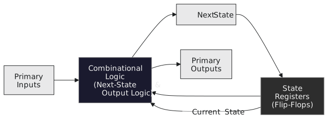
What you will build
By the end of the module you will have designed and simulated three complete machines: a traffic light controller, a serial pattern detector that raises a flag when it sees the sequence 1011 in a bit stream, and a vending machine controller that takes coins, tracks a total, dispenses and gives change. Each goes from state diagram to equations to Verilog.
The sections
| Section | Topic | Contents |
|---|---|---|
| 3.1 | Latches and flip-flops | Bistability, the SR and D latches, the D flip-flop, JK and T types, setup and hold |
| 3.2 | Synchronous and asynchronous design | Clocks and their distribution, the synchronous discipline, why asynchronous design is dangerous, metastability |
| 3.3 | Finite state machines | Moore and Mealy, state diagrams and tables, encoding, the synthesis procedure, Verilog, two worked designs |
| 3.4 | Registers and shift registers | Parallel load, serial shift, applications, the universal shift register |
| 3.5 | Counters | Ripple and synchronous counters, modulo-N, up/down, Gray code, applications |
| 3.6 | Memory elements | Register files, SRAM, DRAM and the memory hierarchy, ROM and flash |
Each section assumes the ones before it. Section 3.1 carries the most weight, and if you already know flip-flops you can move quickly through the early articles, but do not skip the timing parameters in 3.1.6; everything in 3.2 rests on them.
A warning about timing
In combinational design, a circuit that is logically right is right; a slow one is merely slow. In sequential design, timing is part of correctness. If the D input changes too close before the clock edge, violating setup time, the flip-flop may capture neither a 0 nor a 1 but sit between them, metastable, for an unpredictable time. If D changes too soon after the edge, violating hold time, the flip-flop captures the new value instead of the old one. Hold violations do not go away when you slow the clock down.
Neither failure shows in a simulation that uses ideal flip-flop models. The design passes every test, synthesises cleanly, and fails in silicon at temperature, or at the edge of the voltage range, or now and then on some data pattern. This module defines every timing parameter properly and derives every constraint, so that by the end you can look at any synchronous circuit and say whether it is correct.
Start with section 3.1, and the question of how silicon can remember anything at all.