Metastability
This is the last article of section 3.2, and it is about the one thing the synchronous discipline cannot remove. Every D flip-flop ever made can end up with its output at a voltage that is neither 0 nor 1, balanced at an unstable point, taking an unpredictable time to fall one way or the other. That is metastability. You cannot buy a flip-flop that does not do it, and you cannot lay it out or slow it down away. Whenever a signal that is not synchronised to the clock enters a flip-flop, there is some probability of it. The job is to make that probability small enough that the expected time between failures is longer than the product will exist.
The physics
A flip-flop’s storage element is a cross-coupled pair of inverters with two stable states and an unstable balance point between them, at about half the supply voltage. Normally D is stable well before the edge, the latch closes with its nodes far from the balance point, and the positive feedback drives them to a rail within the clock-to-Q delay.
If D changes inside the setup window, the latch can close with its nodes near the balance point. The feedback still amplifies whatever small imbalance there is, but slowly at first, and exponentially:
$$V(t) = \frac{V_{DD}}{2} + V_\epsilon e^{t/\tau}$$
where $V_\epsilon$ is the initial offset and $\tau$ is the flip-flop’s metastability time constant, a property of the process. It is roughly 120 to 200 ps at 180 nm, 20 to 40 ps at 28 nm and 10 to 20 ps at 7 nm; smaller transistors have more gain-bandwidth and resolve faster.
The probability that the output is still unresolved after a time $t$ is
$$P(t) = e^{-t/\tau}$$
It falls off exponentially, so a metastable flip-flop almost always resolves within a few time constants. Almost. The tail never reaches zero.
The window
Not every change near the edge is equally dangerous. A change 1 ps inside the window is far more likely to cause trouble than one 50 ps inside it. The metastability window $t_w$ is the width of the interval around the edge in which a transition can cause metastability, roughly the setup plus hold time: perhaps 50 to 100 ps for a modern cell.
MTBF
The mean time between failures of a synchroniser is the expected time between events where a metastable flip-flop fails to resolve within the time available and passes an undefined value downstream:
$$MTBF = \frac{e^{t_r/\tau}}{f_{clk} , f_{data} , t_w}$$
Here $t_r$ is the resolution time available, which in a synchroniser is the clock period minus the setup time of the next flip-flop; $f_{clk}$ is the clock frequency; $f_{data}$ is the rate at which the asynchronous input changes; and $t_w$ is the window.
Take a 1 GHz clock, an input changing at 10 MHz, a 7 nm process with $\tau = 15$ ps, and $t_w = 80$ ps with a setup time of 80 ps. With one flip-flop, $t_r = 1000 - 80 = 920$ ps:
$$MTBF = \frac{e^{920/15}}{10^9 \times 10^7 \times 80 \times 10^{-12}} = \frac{e^{61.3}}{8 \times 10^5} \approx 5 \times 10^{20} \text{ s}$$
That is around $10^{13}$ years, a thousand times the age of the universe. At 1 GHz a single well-designed stage is, in practice, safe.
The picture changes at higher clock rates, because the exponent shrinks. At 4 GHz, $t_r = 250 - 80 = 170$ ps and $e^{170/15} \approx 8 \times 10^4$. The denominator is now $4 \times 10^9 \times 10^7 \times 80 \times 10^{-12} = 3.2 \times 10^6$:
$$MTBF \approx \frac{8 \times 10^4}{3.2 \times 10^6} \approx 0.03 \text{ s}$$
A single stage at 4 GHz fails about forty times a second. Add a second flip-flop and the resolution time becomes $2 \times 250 - 80 = 420$ ps, $e^{28} \approx 1.4 \times 10^{12}$, and the MTBF is about $4.5 \times 10^5$ s, five days. Still not good enough for a ten-year product. A third stage gives $t_r = 670$ ps, $e^{44.7} \approx 2.6 \times 10^{19}$, and an MTBF of about $8 \times 10^{12}$ s, a quarter of a million years. That is why fast designs use three-stage synchronisers, and why the number of stages is a calculation and not a habit.
The two-flop synchroniser
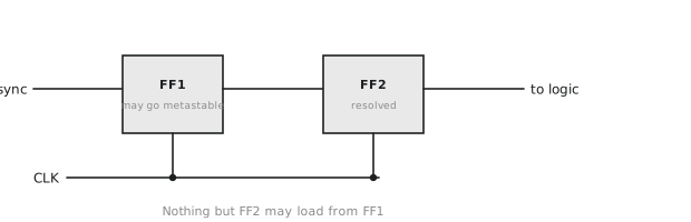
The standard circuit for bringing an asynchronous signal into a clock domain is two flip-flops in series on the destination clock (Figure 1).
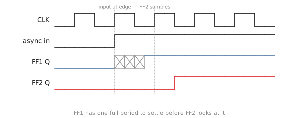
The first flip-flop may go metastable when the input changes near its edge. It then has a full period, less the second flip-flop’s setup time, to resolve before the second flip-flop samples it (Figure 2). If it resolves in time, which it does with probability $1 - e^{-t_r/\tau}$, the second flip-flop delivers a clean value one cycle later. A third stage, where needed, adds another period of resolution and another cycle of latency.
The fan-out rule
The most commonly broken rule about synchronisers is this one: the first flip-flop’s output goes to the second flip-flop’s D input and nowhere else.
It seems harmless to let something else look at it too; after all, it will resolve. But while it is metastable it sits at an intermediate voltage, and a gate that reads it maps that voltage through its own transfer curve to some other intermediate voltage, and may read it as a 1 while the second flip-flop reads it as a 0. Two consumers of the same metastable event can disagree about what happened, and that inconsistency is one of the most common bugs in designs with several users of one control signal. Everything that needs the synchronised signal takes it from the second flip-flop.
Multi-bit crossings
One-bit synchronisers are well understood. Buses are where clock domain crossing goes wrong. Put an 8-bit value through eight independent synchronisers and each bit resolves on its own: bit 3 may take its new value one cycle before bit 0, and for that cycle the destination sees a mixture of old and new bits that was never a valid value. If it is an address, the result is garbage.
There are three correct approaches. For values that change by one step at a time, such as FIFO pointers, encode them in Gray code, so that only one bit changes per step and a per-bit synchroniser is safe. For general data, synchronise a single valid flag and hold the data stable in the source domain until the flag has been seen; the destination samples the bus only after the synchronised flag, by which time every bit has been stable for at least a source cycle. For streaming data, use a dual-clock FIFO, which is built from Gray-coded pointers and is the standard solution for high-throughput crossings. Module 7 builds one.
Practice Exercise
Problem 1. A 500 MHz design uses 7 nm flip-flops with $\tau = 12$ ps, $t_w = 60$ ps and a setup time of 60 ps. The asynchronous input changes at up to 50 MHz. Find the MTBF with one stage and with two.
Solution
One stage: $t_r = 2000 - 60 = 1940$ ps, $e^{1940/12} = e^{161.7} \approx 10^{70}$, denominator $5 \times 10^8 \times 5 \times 10^7 \times 60 \times 10^{-12} = 1.5 \times 10^6$, so MTBF is about $10^{64}$ s. Two stages: $t_r = 3940$ ps, and the MTBF is around $10^{136}$ s. At 500 MHz in this process even one stage is far beyond any lifetime; the second is there for margin and for the fan-out discipline.
Problem 2. A 16-bit counter that increments by one each cycle has to cross from 125 MHz to 1 GHz. Why do sixteen separate synchronisers fail, and what works?
Solution
Going from 2047 to 2048 flips eleven bits at once. Sixteen independent synchronisers resolve on different cycles, and the destination can see 2049 or 2046 or anything else made of a mixture of old and new bits. Convert to Gray code in the source domain, where only one bit changes per increment, synchronise each bit, and convert back in the destination:
// source domain: binary to Gray
assign count_gray = count_bin ^ (count_bin >> 1);

// destination domain: two flip-flops per bit
always_ff @(posedge clk_fast) begin
    sync1 <= count_gray;
    sync2 <= sync1;
end

// Gray back to binary
always_comb begin
    count_bin_rx[15] = sync2[15];
    for (int i = 14; i >= 0; i--)
        count_bin_rx[i] = count_bin_rx[i+1] ^ sync2[i];
end
The decoded value is always either the old count or the new one, never a hybrid.
Problem 3. A synchroniser has a mux between its two flip-flops to allow a bypass for same-domain signals. What is wrong with it?
always_ff @(posedge clk) ff1_q <= async_in;
always_ff @(posedge clk) ff2_q <= bypass_mode ? same_domain_in : ff1_q;
assign sync_out = ff2_q;
Solution
There is logic between the two flip-flops. The mux delay comes off the resolution time, which reduces the MTBF exponentially, and if bypass_mode changes while ff1_q is metastable the mux output is undefined. Put the mux after the second flip-flop, where it operates on a resolved signal:
always_ff @(posedge clk) ff1_q <= async_in;
always_ff @(posedge clk) ff2_q <= ff1_q;
assign sync_out = bypass_mode ? same_domain_in : ff2_q;
Section 3.3 turns to the main use of all this, the finite state machine, starting with what a state machine is and the two kinds, Moore and Mealy.