Worked Example: A Serial Pattern Detector
The second worked example is harder than the traffic light, not because it has more states but because of what happens when one match can overlap the start of the next.
Detecting a pattern in a serial stream is what every communications block does. A UART receiver looks for a start bit, eight data bits and a stop bit. USB’s encoding needs the receiver to count consecutive 1s for bit stuffing. HDLC frames begin and end with 01111110, and the receiver has to spot it and strip stuffed bits from the data. All of these are the circuit in this article with a different pattern.
Specification
Input x, one bit per clock. Output z, high for one cycle when the last four bits received were 1011, in the cycle after the final 1 arrives. Matches may overlap: in …10111011… the second match’s first bit is the first match’s last bit.
States
A Moore machine whose states record how much of 1011 has been matched:
| State | Matched | z |
|---|---|---|
| S0 | nothing | 0 |
| S1 | 1 | 0 |
| S2 | 10 | 0 |
| S3 | 101 | 0 |
| S4 | 1011 | 1 |
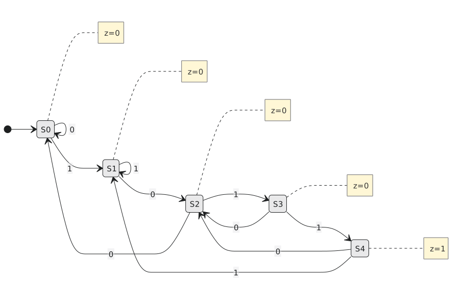
The transitions follow from one question, asked at every state for each input: after this bit, what is the longest tail of the received stream that is also a head of 1011?
From S0: 0 stays; 1 to S1.
From S1, having 1: 0 gives 10, to S2; 1 gives 11, whose only useful tail is 1, stay.
From S2, having 10: 0 gives 100, nothing, to S0; 1 gives 101, to S3.
From S3, having 101: 0 gives 1010, whose tail 10 is a head of 1011, to S2; 1 gives 1011, to S4.
From S4, having 1011: 0 gives a tail of 10, to S2; 1 gives a tail of 1, to S1.
The S3 to S2 and S4 to S2 and S4 to S1 transitions are the overlap. Without them the machine would need four fresh bits after every near miss and would miss matches. This is the same reasoning as the failure function in the Knuth-Morris-Pratt string search: “if the match fails here, what is the longest prefix of the pattern that I have still got?” Hardware pattern detectors and software string search are the same idea.
The Mealy version
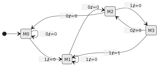
A Mealy machine does not need S4. The transition from S3 on a 1 can carry the output, and it can go straight to S1, since the matching 1 is also the start of a possible next match (Figure 2).
| Moore | Mealy | |
|---|---|---|
| states | 5 | 4 |
| flip-flops | 3 | 2 |
| output | registered, in S4, the cycle after the last bit | combinational, in the same cycle as the last bit |
| glitches | none | follow glitches on x |
Table and encoding
| State | x | Next | z |
|---|---|---|---|
| S0 | 0 | S0 | 0 |
| S0 | 1 | S1 | 0 |
| S1 | 0 | S2 | 0 |
| S1 | 1 | S1 | 0 |
| S2 | 0 | S0 | 0 |
| S2 | 1 | S3 | 0 |
| S3 | 0 | S2 | 0 |
| S3 | 1 | S4 | 0 |
| S4 | 0 | S2 | 1 |
| S4 | 1 | S1 | 1 |
Binary: S0 = 000, S1 = 001, S2 = 010, S3 = 011, S4 = 100, with 101, 110 and 111 as don’t-cares.
| $Q_2 Q_1 Q_0$ | x | $D_2 D_1 D_0$ | z |
|---|---|---|---|
| 000 | 0 | 000 | 0 |
| 000 | 1 | 001 | 0 |
| 001 | 0 | 010 | 0 |
| 001 | 1 | 001 | 0 |
| 010 | 0 | 000 | 0 |
| 010 | 1 | 011 | 0 |
| 011 | 0 | 010 | 0 |
| 011 | 1 | 100 | 0 |
| 100 | 0 | 010 | 1 |
| 100 | 1 | 001 | 1 |
The equations
$D_2$ is 1 only when the next state is S4, from S3 on a 1. With the don’t-care at 111:
$$D_2 = Q_1, Q_0, x$$
$D_1$ is 1 when the next state is S2 or S3: from S1, S3 or S4 on a 0, and from S2 on a 1. On the map, the rows with $x = 0$ and either $Q_2$ or $Q_0$ set cover the first three (using the don’t-cares at 101, 110 and 111), and $Q_1 \overline{Q_0} x$ covers the last (using 110):
$$D_1 = \overline{x},(Q_2 + Q_0) + x, Q_1, \overline{Q_0}$$
$D_0$ is 1 when the next state is S1 or S3: from S0, S1 or S4 on a 1, and from S2 on a 1, but not from S3 on a 1. Everything is under $x$. The three states S0, S1 and S4 have $Q_1 = 0$; S2 has $Q_0 = 0$; S3, the exception, has both set:
$$D_0 = x,(\overline{Q_1} + \overline{Q_0})$$
$z$ is 1 only in S4, and with the don’t-cares at 101, 110 and 111:
$$z = Q_2$$
If you would rather not rely on unused codes never occurring, $z = Q_2 \overline{Q_1},\overline{Q_0}$ is the safe version at the cost of a gate.
A simulation
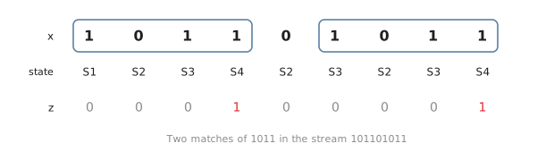
Feed in 1 0 1 1 0 1 0 1 1 (Figure 3).
| After bit | x | State | z |
|---|---|---|---|
| reset | S0 | 0 | |
| 1 | 1 | S1 | 0 |
| 2 | 0 | S2 | 0 |
| 3 | 1 | S3 | 0 |
| 4 | 1 | S4 | 1 |
| 5 | 0 | S2 | 0 |
| 6 | 1 | S3 | 0 |
| 7 | 0 | S2 | 0 |
| 8 | 1 | S3 | 0 |
| 9 | 1 | S4 | 1 |
Bits 1 to 4 are 1011 and so are bits 6 to 9. After the first match the 0 at bit 5 took the machine to S2, not S0, and that is what let it find the second match without a fresh start.
Practice Exercise
Problem 1. Redesign the detector for 1001.
Solution
S0 none, S1 “1”, S2 “10”, S3 “100”, S4 “1001”. S0: 0 stays, 1 to S1. S1: 0 to S2, 1 stays. S2: 0 to S3, 1 to S1 (tail 101, useful tail 1). S3: 0 to S0 (tail 1000, nothing), 1 to S4. S4: 0 to S2 (tail 10), 1 to S1 (tail 1). Same shape, different overlap edges.
Problem 2. Write the Mealy machine’s table.
Solution
| State | x | Next | z |
|---|---|---|---|
| M0 | 0 | M0 | 0 |
| M0 | 1 | M1 | 0 |
| M1 | 0 | M2 | 0 |
| M1 | 1 | M1 | 0 |
| M2 | 0 | M0 | 0 |
| M2 | 1 | M3 | 0 |
| M3 | 0 | M2 | 0 |
| M3 | 1 | M1 | 1 |
Eight rows against ten, and the output is on the M3 to M1 edge, in the same cycle as the final bit.
Problem 3. Run the Moore detector on 1 1 0 1 1.
Solution
S1, S1, S2, S3, S4. One match, from bits 2 to 5. The first 1 got the machine to S1 and the second 1 kept it there; the match is built on the second.
The last worked example is a vending machine, and it is the one where the pure state machine approach stops being sensible.