Worked Example: A Traffic Light Controller
This is the first of three worked examples that run the eight-step flow from the last article end to end. It starts with something everyone knows: a traffic light.
Specification
An intersection has north-south and east-west traffic. A timer pulses timer = 1 for one cycle when the current phase has run its time. A pedestrian button sets ped_req, which is latched until served.
Inputs: timer and ped_req, one bit each.
Outputs: NS_green, NS_yellow, NS_red, EW_green, EW_yellow, EW_red.
| State | NS | EW | Leaves when |
|---|---|---|---|
| NS_GO | green | red | timer |
| NS_WARN | yellow | red | timer |
| EW_GO | red | green | timer |
| EW_WARN | red | yellow | timer |
| PED_CROSS | red | red | timer |
The normal cycle is NS_GO, NS_WARN, EW_GO, EW_WARN and back. If ped_req is set when NS_WARN’s timer fires, PED_CROSS is inserted before EW_GO. From PED_CROSS the machine always goes to EW_GO.
Name states after what they mean, not after their codes. NS_GO is documentation; state_000 is not, and in six months you will be glad of it.
State diagram
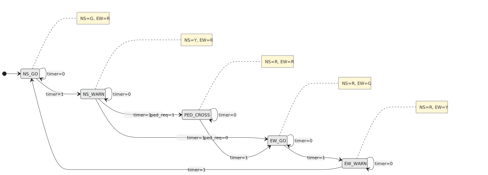
It is a Moore machine: the lamps depend only on the state.
Transition table
With timer = 0 every state stays where it is, so only the timer = 1 rows are interesting:
| State | timer | ped_req | Next |
|---|---|---|---|
| NS_GO | 1 | X | NS_WARN |
| NS_WARN | 1 | 0 | EW_GO |
| NS_WARN | 1 | 1 | PED_CROSS |
| EW_GO | 1 | X | EW_WARN |
| EW_WARN | 1 | X | NS_GO |
| PED_CROSS | 1 | X | EW_GO |
ped_req only matters in NS_WARN.
Encoding
Five states need three flip-flops:
| State | $Q_2 Q_1 Q_0$ |
|---|---|
| NS_GO | 000 |
| NS_WARN | 001 |
| EW_GO | 010 |
| EW_WARN | 011 |
| PED_CROSS | 100 |
Codes 101, 110 and 111 are unused and are don’t-cares.
Next-state logic
Write $T$ for timer and $P$ for ped_req. Each next-state bit has a hold part (the current bit when $T = 0$) and a transition part (when $T = 1$).
$D_2$ is 1 when the next state is PED_CROSS, which happens from NS_WARN with $T = 1$ and $P = 1$, or when holding in PED_CROSS with $T = 0$:
$$D_2 = \overline{Q_2},\overline{Q_1}, Q_0, T, P + Q_2, \overline{T}$$
$D_1$ is 1 when the next state is EW_GO or EW_WARN. With $T = 1$ that is from NS_WARN with $P = 0$, from EW_GO, or from PED_CROSS. With $T = 0$ it is holding in EW_GO or EW_WARN, that is $Q_1 = 1$ (using the don’t-cares at 110 and 111):
$$D_1 = T \left( \overline{Q_2},\overline{Q_1}, Q_0, \overline{P} + \overline{Q_2}, Q_1, \overline{Q_0} + Q_2 \right) + \overline{T}, Q_1$$
The $Q_2$ term uses the don’t-cares at 101, 110 and 111 to cover PED_CROSS with a single literal.
$D_0$ is 1 when the next state is NS_WARN or EW_WARN. With $T = 1$ that is from NS_GO or EW_GO, the two states with $Q_2 = 0$ and $Q_0 = 0$; with $T = 0$ it is holding in NS_WARN or EW_WARN, $Q_2 = 0$ and $Q_0 = 1$:
$$D_0 = \overline{Q_2},\overline{Q_0}, T + \overline{Q_2}, Q_0, \overline{T} = \overline{Q_2},(Q_0 \oplus T)$$
This last one is neat: outside PED_CROSS, the low bit toggles whenever the timer fires.
Output logic
| State | code | NS_G | NS_Y | NS_R | EW_G | EW_Y | EW_R |
|---|---|---|---|---|---|---|---|
| NS_GO | 000 | 1 | 0 | 0 | 0 | 0 | 1 |
| NS_WARN | 001 | 0 | 1 | 0 | 0 | 0 | 1 |
| EW_GO | 010 | 0 | 0 | 1 | 1 | 0 | 0 |
| EW_WARN | 011 | 0 | 0 | 1 | 0 | 1 | 0 |
| PED_CROSS | 100 | 0 | 0 | 1 | 0 | 0 | 1 |
Reading from the codes:
$$\text{NS_green} = \overline{Q_2},\overline{Q_1},\overline{Q_0} \qquad \text{NS_yellow} = \overline{Q_2},\overline{Q_1}, Q_0 \qquad \text{NS_red} = Q_2 + Q_1$$
$$\text{EW_green} = \overline{Q_2}, Q_1, \overline{Q_0} \qquad \text{EW_yellow} = \overline{Q_2}, Q_1, Q_0 \qquad \text{EW_red} = \overline{Q_1}$$
NS_red is on in 010, 011 and 100, which is $Q_1$ or $Q_2$. EW_red is on in 000, 001 and 100, all of which have $Q_1 = 0$.
A simulated cycle
Figure 2 traces NS_GO, NS_WARN, PED_CROSS, EW_GO, EW_WARN, with the button pressed during NS_GO.
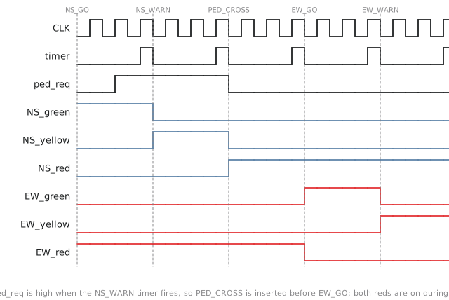
The timer pulse at the end of each phase moves the state on. Because ped_req is set when NS_WARN’s timer fires, the machine goes to PED_CROSS rather than EW_GO, and during PED_CROSS both reds are on. When its timer fires, EW_GO follows as normal.
Practice Exercise
Problem 1. Change the specification so that a pedestrian request during EW_GO also gets a crossing, inserted between EW_WARN and NS_GO. How many states now?
Solution
Add PED_CROSS_2 with EW_WARN going to it on timer and ped_req, and to NS_GO on timer alone; PED_CROSS_2 goes to NS_GO. The two crossing states have the same outputs but different successors, so they cannot be merged. Six states, still three flip-flops.
Problem 2. The design has no reset. What if the register powers up as 111?
Solution
111 is undefined, and the output logic could show green both ways. Two things are needed: a power-on reset that forces the state to NS_GO, and a defined transition out of every unused code, which in Verilog is the default branch of the case statement. A real controller would go to a flashing-yellow fault state rather than straight into the cycle, but that is beyond this specification.
Problem 3. Check $\text{EW_red} = \overline{Q_1}$ on the five valid states, and see what it does in the unused ones.
Solution
000, 001 and 100 have $Q_1 = 0$ and EW_red on; 010 and 011 have $Q_1 = 1$ and EW_red off. All correct. In 101 EW_red is on, which is at least safe; in 110 and 111 it is off, which could be unsafe depending on the other outputs. That is why unused codes need a reset path.
The next example is a serial pattern detector, where the difficulty is not the states but what happens when one match overlaps the next.