Modulo-N Counters
The counters so far wrap at a power of two. Seconds wrap at 60, a display digit at 10, hours at 12 or 24, a stepper motor at 48 positions. A modulo-N counter counts 0 to $N-1$ and then returns to 0. There are three ways to build one.
Clear on N-1
Take a binary counter with enough bits, $\lceil \log_2 N \rceil$, and add a synchronous clear. Decode the count $N-1$ and feed that into the clear. When the counter reads $N-1$ the clear is high, so at the next edge it loads 0 instead of $N$ (Figure 1).
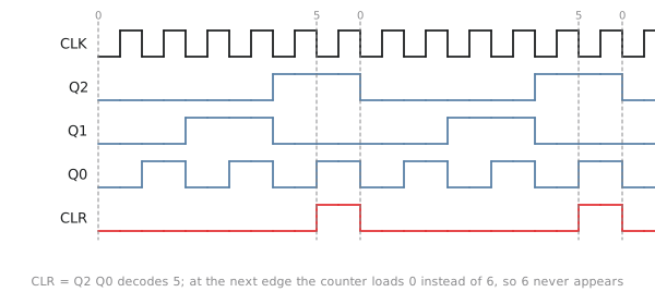
For a mod-6 counter, $N-1 = 5 = 101$, so
$$CLR = Q_2 \overline{Q_1} Q_0$$
and the sequence is 0, 1, 2, 3, 4, 5, 0. Each value, including 5, is held for exactly one cycle and 6 never appears. You can usually shorten the decode. The counter never gets past 5, so among the values it does reach, 5 is the only one with $Q_2 = 1$ and $Q_0 = 1$, and $CLR = Q_2 Q_0$ is enough.
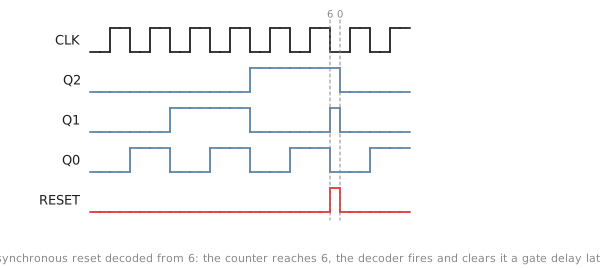
Two things people get wrong here. The first is to decode $N$ instead of $N-1$. If you clear on 6, the counter reads 6 for a full cycle before it clears, and you have built a mod-7 counter. The second is to use the asynchronous reset pin (Figure 2). Decode 6, feed it to the async clear, and the counter does reach 6, for as long as it takes the decoder to see it and the flip-flops to clear, a few nanoseconds. Then the count is 0, the decoder output drops, and the reset releases. It works, in the sense that the count sequence has six states, but the state 6 is really there, on real wires, and the reset pulse is only as wide as a couple of gate delays. If one flip-flop clears before the others the pulse can end before they all see it. This was a common trick with 7490-series parts and it is the wrong way to do it in anything synchronous.
Preload
The second way uses the terminal count and a parallel load instead of a clear. Let the counter run up to its natural top, $2^k - 1$, and when it gets there load $2^k - N$ instead of wrapping to 0. A 3-bit mod-6 counter loads 2 and runs 2, 3, 4, 5, 6, 7, 2. There is no decoder to design, because the terminal count is already there. The cost is that the count does not start at 0, so if you are displaying it you have to subtract the offset. Down-counters with a preload are common in timer peripherals: load the period, count to zero, reload.
Custom next-state logic
The third way is to treat the counter as a state machine with $N$ states and derive the next-state logic from a state table and maps, as in section 3.3. For a mod-6 counter in binary encoding the unused states 6 and 7 are don’t-cares. This gives the smallest logic and it is the most work, and for anything beyond a few bits the first method is the one to use. It is what synthesis produces when you write if (count == N-1) count <= 0; else count <= count + 1;.
Two decade counters
A mod-10 counter counts 0 to 9 and is the building block of a BCD display. Four flip-flops, clear on $9 = 1001$. Among 0 to 9, only 9 has both $Q_3$ and $Q_0$ set, so
$$CLR_{10} = Q_3 Q_0$$
A mod-12 counter clears on $11 = 1011$. The values 0 to 11 with $Q_3 = 1$ are 8, 9, 10, 11, and of those only 11 has $Q_1 Q_0 = 11$, so
$$CLR_{12} = Q_3 Q_1 Q_0$$
The shortened decodes depend on the counter never reaching the unused states. If it can start in one of them at power-up, a full decode or a reset takes care of that.
Cascading BCD counters into a clock
A clock has seconds 0 to 59, minutes 0 to 59 and hours 0 to 23. Each two-digit field is a mod-10 units counter followed by a mod-6 tens counter, and the terminal count of each stage enables the next (Figure 3). All of them are on the same clock, and the enables are computed combinationally before each edge, so the whole chain is synchronous. A 1 Hz clock into the seconds units gives you a clock.
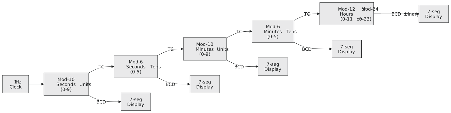
The hours field is the awkward one. In 24-hour form it is a mod-24 counter: units mod-10, tens mod-3, but the wrap happens at 23, not at 29, so the clear condition is tens $= 2$ and units $= 3$, applied to both digits at once. In 12-hour form the display runs 12, 1, 2, …, 11, 12, which is a mod-12 counter that does not start at 0. The simplest way is to count 0 to 11 internally and display 12 in place of 0.
Practice Exercise
Problem 1. Design a mod-7 counter with a synchronous clear. Give the clear equation and check that 7 never appears.
Solution
Three flip-flops, clear on $6 = 110$: $CLR = Q_2 Q_1 \overline{Q_0}$. Among 0 to 6 only 6 has $Q_2 Q_1 = 11$, so $CLR = Q_2 Q_1$ is enough. Sequence 0, 1, 2, 3, 4, 5, 6, 0; the counter goes from 6 straight to 0 and 7 is never reached.
Problem 2. A 12-hour clock displays 12, 1, 2, …, 11 with two BCD digits. What is the load condition and what value is loaded?
Solution
Detect 12: tens digit $= 1$ and units digit $= 2$. Among the values that occur, tens is either 0 or 1 and units is 0 to 9, so $tens_0 \cdot units_1$ is enough (12 is the only value with tens $= 1$ and $units_1 = 1$, since 10 and 11 have $units_1 = 0$). On that condition, load tens $= 0$, units $= 1$. Alternatively count 0 to 11 in binary and translate 0 to “12” at the display.
Problem 3. Compare a mod-6 counter built from a 3-bit binary counter with synchronous clear against one designed as a state machine from maps.
Solution
Both use three flip-flops. The binary counter needs the two toggle ANDs, the clear decode $Q_2 Q_0$ and a mux or AND in front of each D to apply the clear, about five gates. The state-machine design, with 6 and 7 as don’t-cares, gives $D_0 = \overline{Q_0},\overline{Q_2}$, $D_1 = Q_1 \oplus Q_0$, $D_2 = Q_2 \overline{Q_0} + Q_1 Q_0$, which is a similar count. For small $N$ the difference is negligible and the binary counter is easier to change; use the state-machine method only when the sequence is not a simple count.
Modulo-N counters count up. The next article is about counters that count down, count in Gray code, or do not count in binary at all.