How Asynchronous Designs Fail
In Module 2 we met combinational hazards: brief wrong values that go away once every path has settled. Sequential hazards are worse. They are not transient outputs but wrong state changes, and the circuit stays in the wrong state for good. This article is about the three main ones, and it explains why asynchronous sequential design is hard and why even a synchronous design has to be careful at its edges.
Races
A race is a situation where the result depends on the order of events that have no guaranteed order.
In an asynchronous state machine the state is held in latches or feedback loops, and when a transition needs two state bits to change, each changes along its own path with its own delay. The machine passes through an intermediate state with one bit changed and the other not, and that intermediate state may be a legitimate state with behaviour of its own.
Take a 2-bit machine going from 00 to 11. Both bits have to flip, and one will be first. Figure 1 shows the two possibilities.
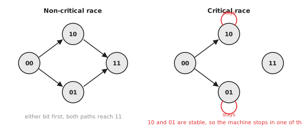
If both intermediate states, 01 and 10, are transit states that continue to 11 under the current input, the race is non-critical. Whichever bit changes first, the machine arrives at 11.
If 01 or 10 is a stable state under the current input, the race is critical. The machine goes to whichever one the faster bit leads to, and stays there. The final state depends on which transistor was faster, which depends on temperature, voltage and the wafer. The design works on the bench at room temperature and fails in the field at the hot, slow corner.
Designers of asynchronous machines spend a great deal of effort on state encoding for this reason, using Gray-code-like assignments where every transition changes one bit, so that no race can be critical. That whole problem does not exist in a synchronous machine, where every state bit changes at the same clock edge.
Essential hazards
Races come from the encoding and can be designed out. The essential hazard cannot. It is a property of the machine’s structure: a feedback path from the state back to the logic that computes the next state has a delay, and if an input changes again before the previous change has gone all the way round the loop, the machine sees the changes out of order and can settle in the wrong state. Three quick transitions on an input, 0 to 1 to 0 to 1, can leave a machine that should be in state 1 in state 0.
The only remedy is to add delay to particular paths so that each input change finishes propagating before the next, and that delay has to be right at every process corner and survive every later change to the circuit. It is not a maintainable way to build things.
A clocked machine cannot have an essential hazard. Setup time guarantees the input is stable before the edge, and the period guarantees the next state is fully computed before the next edge. The clock enforces the ordering that an asynchronous circuit has to engineer by hand.
Reset release
Even a fully synchronous design has one asynchronous element in nearly every flip-flop: the reset input. It is the most common source of initialisation bugs in commercial chips.
The reset comes from outside the domain, from a supervisor chip or a button, and it is released at a time that has nothing to do with the clock. If the release lands in the setup-hold window of an edge, the flip-flop is being told to leave reset and to sample D at nearly the same moment, and it can go metastable on its first working cycle. Because that flip-flop feeds others, the metastable value can spread, and the design starts from an unknown state instead of a known one.
The standard circuit is the reset synchroniser from the last article: assert asynchronously, release synchronously. Figure 2 shows its timing.
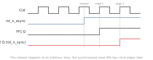
When the raw reset asserts, both flip-flops clear at once and the synchronised reset is low immediately. When it releases, the first flip-flop captures its constant 1 on the next edge, the second captures that on the edge after, and the design leaves reset on a clock edge, two cycles after the raw release. Two cycles is nothing next to the time a PLL takes to lock or a memory takes to initialise.
Works on my bench
What makes these failures so costly is that they depend on the environment. Process variation, temperature and supply voltage all change delays, and a race or an essential hazard fails only when one path becomes faster than another by enough. At the typical corner there may be tens of picoseconds of margin; at the slow corner, none. The chip passes every test on the bench and fails in a cold car with a weak battery. And an asynchronous path that is not constrained as a clock domain crossing is invisible to static timing analysis, so the negative margin never appears in any report. Fixing it after tape-out means a mask change.
In a synchronous design the same path would be checked against the period at every corner, and a hold margin of minus fifteen picoseconds would show up as a red line in the timing report before the chip was ever made.
What this means for a synchronous designer
Three things. First, recognise the asynchronous elements inside your synchronous design: every asynchronous reset, every unsynchronised input, every gated clock without a proper cell, and treat each one with the care a full asynchronous design would need. Second, understand why clock domain crossings are hard: a crossing is a small asynchronous interface between two synchronous domains, with exactly these failure modes, and the synchroniser is the answer to them. Third, keep the timing constraints complete. Missing clock definitions and unconstrained asynchronous paths are how these bugs escape.
Practice Exercise
Problem 1. States are encoded IDLE = 00, WAIT = 01, ACTIVE = 10, DONE = 11. Is the transition IDLE to ACTIVE a critical race?
Solution
00 to 10 changes only one bit, so there is no race at all. A transition from IDLE to DONE, 00 to 11, would pass through 01 or 10, and would be a critical race if either of those is stable for the input that triggered it, and non-critical if both continue to 11. A Gray-code order, 00, 01, 11, 10, avoids the question by changing one bit per step.
Problem 2. Sketch the reset synchroniser waveforms when the raw reset happens to release exactly on a clock edge. How many cycles does the release take?
Solution
The first flip-flop captures 1 at the next edge and the second one at the edge after that, so the synchronised reset releases two cycles after the raw release. That latency is negligible against the hundreds of cycles most systems spend waiting for PLLs and memories at start-up.
Problem 3. Can essential hazards be removed by matching all the path delays with buffers?
Solution
Not reliably. Delays matched at one corner diverge at others, because different gates scale differently with process, voltage and temperature. Temperature is not uniform across a die. Ageing shifts delays at different rates in different places. And finding every hazardous path needs exhaustive analysis that does not scale. The clock solves the problem by giving every path the same budget and letting timing analysis check it at every corner.
The last article in this section is about the failure that no amount of discipline removes, only manages: metastability, and how to make it rare enough not to matter.