Digital Design & Verilog: From Basics to Hero
What This Course Is
This is the course that takes you from “I’ve heard of Verilog” to “I can design, simulate, and verify a working RTL block.” It does not skip the foundations. It does not assume you already know hardware. It builds everything from the ground up — and by the end, you will have designed a UART, an SPI controller, and the beginnings of a processor core.
The course is structured as ten modules. The first three cover digital logic theory — the mathematics and reasoning that underlie all hardware. Starting from Module 4, you write Verilog. By Module 7 you are building production-quality RTL patterns. Modules 9 and 10 introduce SystemVerilog and capstone projects.
Who this is for: Electrical engineering students, hobbyist FPGA designers, software engineers moving into hardware, and working engineers who want to fill in the foundational gaps.
Course Map
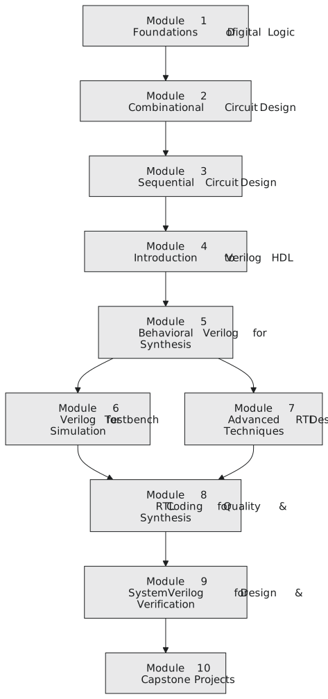
Modules
Module 1 — Foundations of Digital Logic
The mathematical and logical bedrock every digital designer must know before writing a single line of code.
| Section | Topics |
|---|---|
| 1.1 Number Systems & Arithmetic | Binary, hex, octal, signed numbers, two’s complement, overflow |
| 1.2 Boolean Algebra | Axioms, theorems, De Morgan’s laws, SOP/POS canonical forms |
| 1.3 Logic Gates & Truth Tables | AND/OR/NOT/NAND/NOR/XOR, CMOS intuition, universal gates |
| 1.4 Karnaugh Maps & Logic Minimization | 2–4 variable K-maps, prime implicants, don’t cares, Quine-McCluskey |
| 1.5 Combinational Building Blocks | MUXes, decoders, encoders, priority encoders, comparators |
25 posts · Start here → Why Does Your Computer Only Know Two Numbers?
Module 2 — Combinational Circuit Design
From gates to functional arithmetic units — adders, subtractors, multipliers, ALUs, and combinational hazards.
| Section | Topics |
|---|---|
| 2.1 Adder Circuits | Half adder, full adder, ripple carry, carry lookahead, carry select |
| 2.2 Subtractors & ALU Design | Two’s complement subtraction, basic ALU |
| 2.3 Multipliers & Shifters | Array multiplier, Wallace tree, barrel shifter |
| 2.4 Hazards in Combinational Logic | Static/dynamic hazards, detection and elimination |
Module 3 — Sequential Circuit Design
Time and state — the concepts that separate a microprocessor from a calculator.
| Section | Topics |
|---|---|
| 3.1 Latches & Flip-Flops | SR latch, D/JK/T flip-flops, setup/hold/propagation delay |
| 3.2 Synchronous vs. Asynchronous Design | Why synchronous design dominates industry |
| 3.3 Finite State Machines | Mealy/Moore, state diagrams, encoding, full FSM design flow |
| 3.4 Registers & Shift Registers | Parallel load, SISO/SIPO/PISO, bidirectional |
| 3.5 Counters | Synchronous/ripple, up/down, modulo-N, Johnson/Ring, decade |
| 3.6 Memory Elements | SRAM/DRAM cells, ROM types, register files |
Module 4 — Introduction to Verilog HDL
The hardware description mindset — modules, ports, data types, structural and dataflow modeling.
| Section | Topics |
|---|---|
| 4.1 Why HDL? The Hardware Mindset | Simulation vs. synthesis, the design/verification flow |
| 4.2 Verilog Language Basics | Modules, ports, wire/reg/parameter, number literals, directives |
| 4.3 Operators | Arithmetic, bitwise, reduction, conditional, == vs === |
| 4.4 Structural Modeling | Module instantiation, port connection, primitive gates, netlists |
| 4.5 Dataflow Modeling | Continuous assignments, assign, when to use and when not to |
Module 5 — Behavioral Verilog for Synthesis
The heart of RTL design — synthesizable constructs that map cleanly to registers and logic.
| Section | Topics |
|---|---|
| 5.1 Procedural Blocks | always vs initial, blocking (=) vs non-blocking (<=) |
5.2 Sensitivity Lists & Combinational always |
always @(*), incomplete sensitivity lists, latch inference |
| 5.3 Conditional & Case Statements | if-else, case/casex/casez, full case, latch prevention |
| 5.4 Loops in Verilog | for/while/repeat/forever, synthesizability rules |
| 5.5 Modeling Flip-Flops & Registers | Synchronous/asynchronous reset styles, enables, clock gating |
| 5.6 Modeling FSMs in Verilog | One/two/three-process styles, one-hot vs binary, safe FSMs |
Module 6 — Verilog for Testbench & Simulation
Design without verification is guesswork — the non-synthesizable subset of Verilog for testing.
| Section | Topics |
|---|---|
| 6.1 Testbench Architecture | Self-checking testbench anatomy, DUT instantiation |
| 6.2 Simulation-Only Constructs | $display/$monitor, file I/O, timing control |
| 6.3 Clocks & Reset Sequences | Clock generation patterns, reset assertion protocols |
| 6.4 Writing Self-Checking Tests | $error, golden reference model, automated comparison |
| 6.5 Waveform Analysis | VCD files, GTKWave, debugging simulation mismatches |
Module 7 — Advanced RTL Design Techniques
The design patterns used in professional ASIC and FPGA engineering.
| Section | Topics |
|---|---|
| 7.1 Parameterized & Scalable Modules | parameter/localparam, generate, parameterized FIFOs |
| 7.2 Arithmetic Circuits in RTL | Signed arithmetic pitfalls, saturation, pipelined arithmetic |
| 7.3 Pipeline Design | Throughput vs latency, pipeline stages, stalls, bubbles, MAC unit |
| 7.4 FIFOs — Synchronous & Asynchronous | Full/empty flags, Gray-code pointers, async FIFO design |
| 7.5 Clock Domain Crossing | Metastability, two-flop synchronizer, multi-bit CDC, handshake |
| 7.6 Low-Power Design Techniques | Clock gating, power gating, operand isolation |
Module 8 — RTL Coding for Quality & Synthesis
Good RTL is functionally correct, readable, and synthesizes to an efficient netlist.
| Section | Topics |
|---|---|
| 8.1 RTL Coding Guidelines & Style | Naming conventions, reset consistency, sim/synth mismatches |
| 8.2 Synthesis-Aware Coding | Priority encoders, resource sharing, guiding the tool |
| 8.3 Timing Constraints & STA Basics | Setup/hold paths, critical path, SDC constraints, synthesis targets |
| 8.4 Common RTL Bugs & Debugging | X-propagation, latch inference, reset problems, multi-driver |
Module 9 — SystemVerilog for Design & Verification
Bridging classic Verilog to the modern industry standard.
| Section | Topics |
|---|---|
| 9.1 SystemVerilog Design Enhancements | logic, always_ff/always_comb, typedef/struct/enum, interfaces |
| 9.2 SystemVerilog Verification Basics | Classes, randomization, constraints, UVM-ready testbench architecture |
| 9.3 Assertions — SVA | Immediate vs concurrent assertions, ##, |->, |=>, properties |
Module 10 — Capstone Projects
Five complete RTL systems built from specification to verified simulation.
| Project | Description |
|---|---|
| Project 1 — 8-bit RISC Processor Core | Instruction set, datapath, control unit, fetch/decode/execute |
| Project 2 — UART Controller | Baud rate generation, FSM transmitter/receiver, self-checking testbench |
| Project 3 — SPI Master Controller | Four SPI modes, CPOL/CPHA, shift register datapath, CS management |
| Project 4 — Synchronous SRAM Controller | Address decoding, read/write timing, parameterized memory model |
| Project 5 — AXI4-Lite Slave Interface | Ready/valid handshake, register file, error response |
Tools Used in This Course
All simulation and synthesis work uses open-source tools:
- Icarus Verilog — Verilog simulator
- Verilator — Fast cycle-accurate simulator
- GTKWave — Waveform viewer
- Yosys — Open-source synthesis
Where to Start
If you are new to digital design, begin at the beginning:
→ Module 1: Foundations of Digital Logic
If you already know digital logic and want to jump into Verilog, Module 4 is your entry point — but have Module 1–3 content nearby for reference.