Synchronous Counters
The ripple counter’s problem had one cause: each flip-flop was clocked by the previous one. Fix that and the whole class of problems goes away.
One clock
In a synchronous counter every flip-flop is on the system clock, and all the bits change at the same edge. There are no intermediate states and nothing to glitch (Figure 1). The cost is that we can no longer let each stage simply follow the one before; combinational logic has to work out, before each edge, which bits should toggle.
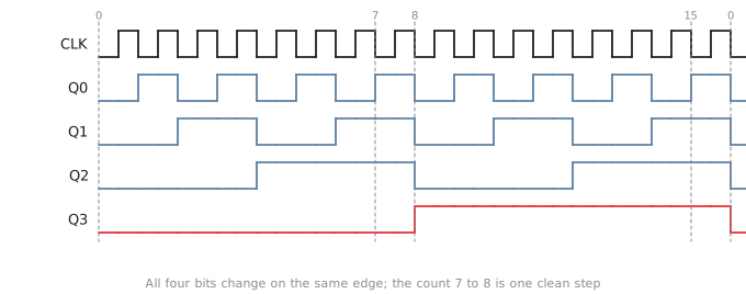
When does each bit toggle
Bit 0 toggles every cycle. Bit 1 toggles when bit 0 is 1. Bit 2 toggles when bits 0 and 1 are both 1. In general bit $i$ toggles when every bit below it is 1:
$$T_0 = 1 \qquad T_1 = Q_0 \qquad T_2 = Q_0 Q_1 \qquad T_3 = Q_0 Q_1 Q_2$$
That is a chain of AND gates, and with T flip-flops (or D flip-flops with $D_i = Q_i \oplus T_i$) it is the whole counter (Figure 2).
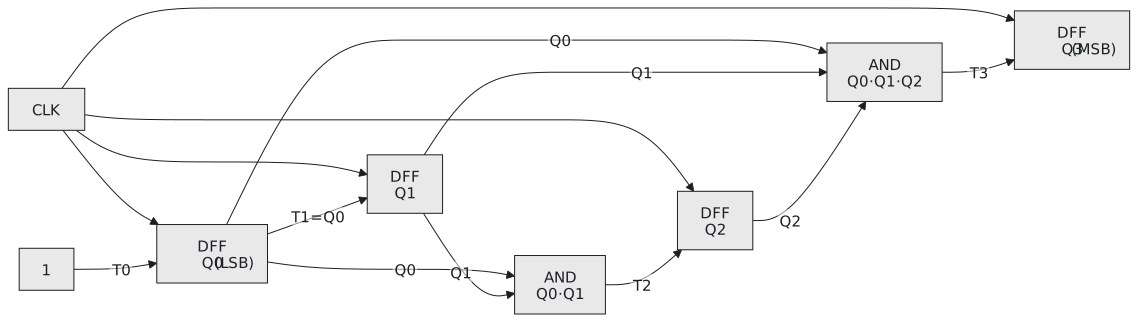
Look at those toggle conditions again. $T_i$ is 1 exactly when there would be a carry into bit $i$ if you added 1 to the count. A counter is an adder with one operand fixed at 1, and its AND chain is the adder’s carry chain. Everything Module 2 said about making carries fast applies to counters.
You can confirm the toggle equations with a map. For $T_1$ as a function of all four bits, the cells with $Q_0 = 1$ are all 1 and the rest all 0, whatever the other bits do, so $T_1 = Q_0$.
Enable
Gate every toggle condition with an enable:
$$T_i = EN \cdot Q_0 Q_1 \cdots Q_{i-1}$$
With EN low nothing toggles and the count holds.
Clear and load
Add a synchronous clear and a parallel load with a priority order, clear first, then load, then count, then hold:
$$D_i = \begin{cases} 0 & CLR \ D[i] & LOAD \ Q_i \oplus T_i & \text{otherwise} \end{cases}$$
This is the same mux-in-front-of-each-flip-flop structure as the registers of section 3.4.
Terminal count
To make a wider counter out of narrower ones you need to know when a stage is about to wrap:
$$TC = Q_3 Q_2 Q_1 Q_0 \cdot EN$$
TC is high when the stage reads 1111 with its enable on, meaning it will go to 0000 at the next edge. Use it as the enable of the next stage. Then when the low stage wraps, the high stage increments at the same edge. Both stages are on the same clock, so the whole thing is still synchronous. The 74HC161 is a 4-bit counter with exactly these signals, and four of them make a 16-bit counter.
Wide counters
The AND for $T_i$ has $i$ inputs, so for a 32-bit counter the top toggle needs a 31-input AND, which is a tree of several levels. As with adders, the fix is lookahead: compute the carry into each bit with two-level logic from the current count, so that the critical path stops growing with width. Synthesis tools do this when you write count + 1.
Practice Exercise
Problem 1. Write the toggle equations for a 3-bit synchronous counter and trace from 5 through the wrap to 1.
Solution
$T_0 = 1$, $T_1 = Q_0$, $T_2 = Q_0 Q_1$.
| $Q_2 Q_1 Q_0$ | $T_2$ | $T_1$ | $T_0$ | next |
|---|---|---|---|---|
| 101 | 0 | 1 | 1 | 110 |
| 110 | 0 | 0 | 1 | 111 |
| 111 | 1 | 1 | 1 | 000 |
| 000 | 0 | 0 | 1 | 001 |
5, 6, 7, 0, 1.
Problem 2. Two 4-bit synchronous counters with enable and terminal count are cascaded into an 8-bit counter. Describe the connection and give the 8-bit terminal count.
Solution
The low stage’s enable is the system enable and its TC is $Q_3 Q_2 Q_1 Q_0 \cdot EN$. The high stage’s enable is that TC. The 8-bit terminal count is the high stage’s TC, which is high only when all eight bits are 1 and the system enable is on.
Problem 3. Compare a 4-bit ripple counter and a 4-bit synchronous counter for logic and for maximum frequency, with $t_{cq} = 2$ ns, an AND gate of 0.5 ns and a setup time of 0.5 ns.
Solution
The ripple counter has no gates but a settling time of $4 \times 2 = 8$ ns, so about 125 MHz. The synchronous counter adds a 2-input AND and a 3-input AND, and its critical path is clock-to-Q plus the AND plus setup, $2 + 0.5 + 0.5 = 3$ ns, so about 330 MHz. Two gates buy nearly three times the speed, and clean outputs.
Binary counters wrap at powers of two. The next article is about counting to any number: 6, 10, 60, 12.