What a State Machine Is
Sections 3.1 and 3.2 gave us flip-flops and the discipline for clocking them. This section is about the main thing we build with them, the finite state machine. A traffic light shows one colour at a time, but it is not reacting to the present moment; it is following a sequence, green, yellow, red, green, and to know what to show next it has to know what it is showing now. That is the whole idea. Some systems cannot be described by their inputs alone. They carry history, and the state machine is the structured way to design them.
The definition
An FSM is a six-tuple
$$\mathcal{M} = (S, I, O, \delta, \lambda, s_0)$$
| Symbol | Meaning |
|---|---|
| $S$ | the finite set of states |
| $I$ | the set of possible inputs |
| $O$ | the set of possible outputs |
| $\delta: S \times I \to S$ | the transition function: given the current state and input, the next state |
| $\lambda$ | the output function, from the state (and possibly the input) to the output |
| $s_0$ | the initial state after reset |
$\delta$ answers “if I am in state $s$ and see input $i$, where do I go?” and $\lambda$ answers “given where I am, what do I output?” Whether $\lambda$ is allowed to look at the input as well as the state is the difference between the two kinds of machine, which the next article covers.
In hardware
Every FSM maps onto the same three blocks (Figure 1).
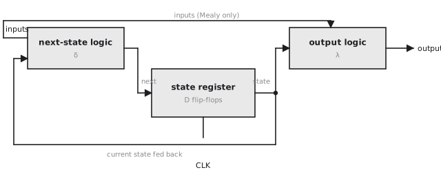
The state register is a set of D flip-flops holding the current state. The next-state logic is combinational, implements $\delta$, and drives the D inputs from the current state and the inputs. The output logic is combinational, implements $\lambda$, and drives the outputs from the state (and for a Mealy machine, the inputs). The clock advances the machine one step per cycle.
The important thing in the picture is that the combinational blocks have no memory. All the memory is in the register. That separation is what makes a state machine analysable: you can always answer “what will this do?” by following the diagram.
The traffic light, formally
States $S = {\text{GREEN}, \text{YELLOW}, \text{RED}}$; input, a timer pulse; outputs, the three lamps; initial state GREEN. Figure 2 is the diagram.
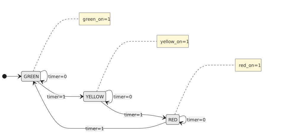
Every state has one outgoing transition for each possible input value. A complete, deterministic machine has exactly one next state for every (state, input) pair.
Why write the states down
Because it forces you to say what the circuit does in every state for every input. A missing transition is an incomplete design; two transitions from one state on the same input are a non-deterministic one. Both are caught on the whiteboard, before simulation, synthesis or silicon. The alternative, sequential logic written without an explicit state model, works for the common cases and fails in the corners the designer never listed, and those are the hardest bugs to find.
Where they are
Everything that moves through phases is one. An elevator has states for floors and door positions. A vending machine’s states record how much money is in. A UART receiver tracks start bit, data bits, parity and stop bit. A TCP connection is defined by the standard as a state machine, CLOSED to SYN_SENT to ESTABLISHED and so on, and every protocol specification, USB, SPI, I²C, PCIe, DDR, contains a state diagram that is not an illustration of the protocol but the protocol itself. Implementing one in hardware means translating that diagram into Verilog.
The biggest state machine you will meet is a processor’s control unit. A simple processor runs every instruction through fetch, decode, execute, memory and write-back, and each phase is a state in which the control unit asserts particular control signals. A multi-cycle processor has a richer diagram with different paths for different instructions. A modern out-of-order core is far more complicated, but it is still state machines, many of them, interacting.
Practice Exercise
Problem 1. A combination lock takes digits one at a time and opens on 3, 7, 2. Draw the state diagram. How many states?
Solution
Four: IDLE, GOT_3, GOT_37 and OPEN. From IDLE, 3 goes to GOT_3 and anything else stays. From GOT_3, 7 goes to GOT_37, 3 stays, anything else returns to IDLE. From GOT_37, 2 goes to OPEN, 3 goes to GOT_3, anything else to IDLE. OPEN asserts unlock and returns to IDLE.
Problem 2. An FSM has three flip-flops. What are the most and fewest states it can have?
Solution
At most $2^3 = 8$. At least, in any useful machine, two. Unused codes are states the machine should never enter, and if it does, on power-up for instance, it should have a defined way out.
Problem 3. With the transition table below, where does the machine end up from S0 after inputs 1, 0, 1, 1?
| State | Input | Next |
|---|---|---|
| S0 | 0 | S0 |
| S0 | 1 | S1 |
| S1 | 0 | S2 |
| S1 | 1 | S0 |
| S2 | 0 | S0 |
| S2 | 1 | S2 |
Solution
S0 to S1 on 1, to S2 on 0, stays on 1, stays on 1. S2.
In the next article we look at the one difference between Moore and Mealy machines and everything that follows from it.