Registers
So far in this module we have built single flip-flops. Nothing real works one bit at a time: a processor handles 32- or 64-bit words, an address is 48 bits, a pixel is 24. This section is about groups of flip-flops that store and move multi-bit values, and it starts with the simplest group, the register.
From one bit to many
Take $N$ D flip-flops and connect them to the same clock. Each stores one bit of an $N$-bit value, and at every rising edge all $N$ are captured together. That is an $N$-bit register. What makes it a register rather than $N$ unrelated flip-flops is that they share the clock, they share the control signals, and the surrounding logic treats the $N$ bits as one value.
The basic version has a data input $D[N-1:0]$, a clock, and an output $Q[N-1:0]$, and loads on every edge: $Q[i] \leftarrow D[i]$ for every $i$. This is a parallel load, all bits at once, as opposed to the serial loading of the next article.
Enable
A register that loads every cycle is rarely what you want. Usually it should hold its value until something explicitly writes it. That needs an enable, and it is implemented as a mux on each D input:
$$D_{actual}[i] = EN ;?; D[i] : Q[i]$$
With the enable low the flip-flop reloads its own output and holds. This matters for power as well as function. Without an enable, all $N$ flip-flops and everything they drive switch on every cycle with random data. With an enable that is high a tenth of the time, the switching activity drops by about the same factor, and the mux costs a gate or two per bit.
Clear
Many registers need to be zeroed at a known moment, an accumulator between operations for instance. A synchronous clear forces zero at the next edge:
$$D_{actual}[i] = CLR ;?; 0 : D[i]$$
Synchronous is the word to notice. The clear takes effect at the next clock edge, which keeps it inside ordinary timing analysis. An asynchronous clear, through the flip-flop’s reset pin, acts immediately, and section 3.2 covered why that needs care.
Putting them together
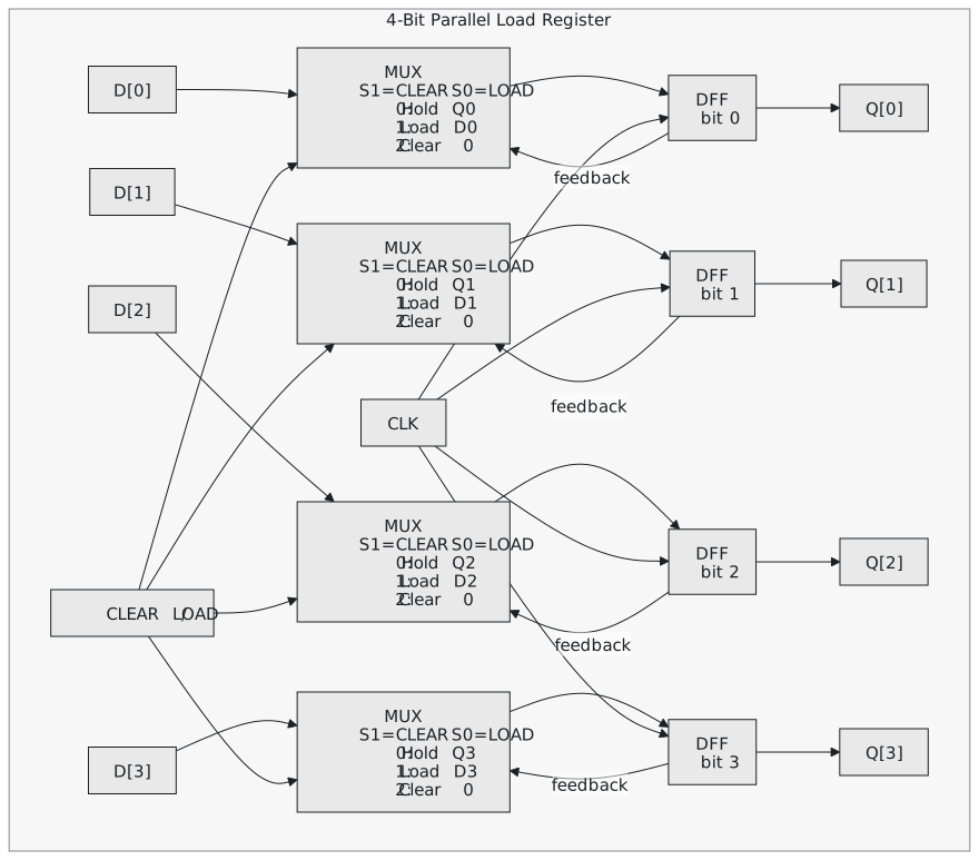
A practical register has enable, clear and load with a priority order. Clear usually wins, since getting to a known state is the more urgent thing:
| CLEAR | LOAD | Result |
|---|---|---|
| 0 | 0 | hold |
| 0 | 1 | load D |
| 1 | X | clear to 0 |
$$D_{actual}[i] = \begin{cases} 0 & CLEAR = 1 \ D[i] & CLEAR = 0,\ LOAD = 1 \ Q[i] & CLEAR = 0,\ LOAD = 0 \end{cases}$$
That is a small mux per bit. Figure 1 shows a 4-bit register with these controls.
Timing
Every bit is captured at the same edge and each bit has its own identical mux in front of it, so there is no path from one bit to another and no bit is a timing outlier. The constraint is the usual one:
$$t_{logic} + t_{mux} + t_{su} \leq T_{clk} - t_{skew}$$
where $t_{logic}$ is whatever combinational logic feeds the D inputs. The register itself is never the critical path; what drives it is.
How many flip-flops
The architectural registers of a 64-bit processor, 31 general-purpose registers plus a program counter and stack pointer, are about 2,100 flip-flops. An out-of-order core adds a physical register file of 128 to 256 entries for renaming, and pipeline registers between every stage, so a single high-performance core can hold tens of thousands of flip-flops just for register storage.
Practice Exercise
Problem 1. Write the D input expression for a 4-bit register with a synchronous enable and a synchronous active-low reset. Which has priority?
Solution
$$D_{actual}[i] = \overline{RESETN} ;?; 0 : (EN ;?; D[i] : Q[i])$$
Reset wins: with RESETN low the register clears whatever EN is.
Problem 2. An 8-bit register at 500 MHz has its enable high one cycle in eight. Roughly how much power does the enable save?
Solution
Without the enable, with random data, each bit toggles about half the time. With the enable, a bit can only change on one cycle in eight, so the activity is about a sixteenth: roughly an eightfold saving in the flip-flops’ dynamic power, less a little for the muxes.
Problem 3. A datapath has 16 general-purpose 32-bit registers. How many flip-flops is that, and what is their leakage at 1 nA and 1.2 V each?
Solution
512 flip-flops, and $512 \times 1,\text{nA} \times 1.2,\text{V} \approx 0.6,\mu\text{W}$. Trivial here, but a large SoC has millions of flip-flops, and ten million of them leak around 12 mW, which is a real part of a mobile power budget.
In the next article the flip-flops are chained so that data moves along them one position per clock: the shift register.