The FSM Design Flow
We now have every piece: diagrams, tables, encodings, Moore and Mealy. This article puts them in the order you use them. The flow below takes a plain-language specification to a working circuit, and it is the same eight steps for a traffic light or a protocol controller. Skipping one is how bugs get in.
- Written specification
- State diagram
- State minimisation
- Transition table
- State encoding
- Next-state logic
- Output logic
- Implementation and verification
Step 1: the specification
Start in words. What are the inputs, what are the outputs, what sequences of behaviour are required, and what timing? This is the only step where ambiguity is allowed, and only briefly: every vague phrase here becomes a missing transition later.
The example for this article: a Moore machine with one input $x$ and one output $z$, where $z$ is 1 exactly when the input was 1 in each of the last two cycles.
Step 2: the diagram
The machine has to remember whether the previous input was 1. Three situations matter:
| State | Meaning | z |
|---|---|---|
| A | previous input was 0, or reset | 0 |
| B | previous input was 1 | 0 |
| C | the previous two inputs were both 1 | 1 |
From A: 0 stays in A, 1 goes to B. From B: 0 goes to A, 1 goes to C. From C: 0 goes to A, 1 stays in C, since the last two inputs are still both 1. Initial state A.
Step 3: minimisation
Two states are equivalent if they give the same output for every input and go to equivalent states for every input. Equivalent states can be merged, and in a machine that is instantiated thousands of times, in a memory controller or a network switch, a wasted flip-flop is real area.
The implication table is the systematic way to find them. Draw a triangle with one cell for each pair of states. First, cross out every pair whose outputs differ. Then, for each remaining pair, write down the pairs of next states they lead to under each input; these are the pairs that must be equivalent for this pair to be equivalent. Then iterate: if any pair written in a cell is itself crossed out, cross out the cell. When nothing changes, the surviving cells are equivalent pairs.
A five-state example:
| State | z | next on 0 | next on 1 |
|---|---|---|---|
| S1 | 0 | S2 | S3 |
| S2 | 0 | S4 | S3 |
| S3 | 1 | S3 | S2 |
| S4 | 0 | S2 | S5 |
| S5 | 1 | S3 | S2 |
S3 and S5 output 1; the rest output 0. Every pair mixing the two groups is crossed out at once. The remaining pairs are (S1, S2), (S1, S4), (S2, S4) and (S3, S5).
(S3, S5): on 0 both go to S3, on 1 both go to S2. No conditions; equivalent.
(S1, S2): on 0 they go to S2 and S4, so this requires (S2, S4); on 1 both go to S3.
(S1, S4): on 0 both go to S2; on 1 they go to S3 and S5, requiring (S3, S5), which holds.
(S2, S4): on 0 they go to S4 and S2, requiring themselves; on 1 to S3 and S5, which holds.
Nothing gets crossed out. S1, S2 and S4 are all equivalent and become one state P; S3 and S5 become Q. Check: from P on 0 every original went to S2 or S4, both P; on 1 to S3 or S5, both Q. From Q on 0 to S3, Q; on 1 to S2, P. The five-state machine is a two-state machine.
Our three-state example has no equivalent states, since A and B differ in where they go on 1 and C has a different output.
Step 4: the table
| State | x | Next | z |
|---|---|---|---|
| A | 0 | A | 0 |
| A | 1 | B | 0 |
| B | 0 | A | 0 |
| B | 1 | C | 0 |
| C | 0 | A | 1 |
| C | 1 | C | 1 |
Step 5: encoding
Three states, two flip-flops, binary: A = 00, B = 01, C = 10. Code 11 is unused and is a don’t-care everywhere.
| $Q_1 Q_0$ | x | $D_1 D_0$ | z |
|---|---|---|---|
| 00 | 0 | 00 | 0 |
| 00 | 1 | 01 | 0 |
| 01 | 0 | 00 | 0 |
| 01 | 1 | 10 | 0 |
| 10 | 0 | 00 | 1 |
| 10 | 1 | 10 | 1 |
| 11 | X | XX | X |
Step 6: next-state logic
One map per next-state bit, with $Q_1$ on the rows and $Q_0 x$ on the columns (Figures 1 and 2).
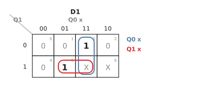
$D_1$ is 1 in cells (01, 1) and (10, 1), and the unused code gives don’t-cares at (11, 0) and (11, 1). Grouping each 1 with a don’t-care:
$$D_1 = Q_0 x + Q_1 x = x (Q_1 + Q_0)$$
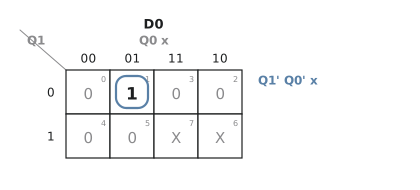
$$D_0 = \overline{Q_1},\overline{Q_0}, x$$
Step 7: output logic
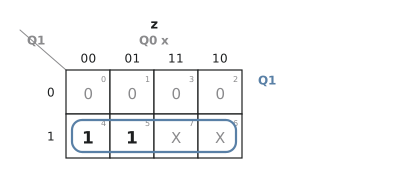
Moore, so $z$ depends on the state only (Figure 3). It is 1 in state 10, and the don’t-care at 11 lets the group grow:
$$z = Q_1$$
Step 8: implementation and check
Two flip-flops, an OR and two ANDs for $D_1$, a three-input AND for $D_0$, and a wire for $z$. Trace it from A with the input sequence 0, 1, 1, 0, 1, 1:
| Cycle | State | x | z | $D_1 D_0$ | Next |
|---|---|---|---|---|---|
| 0 | A 00 | 0 | 0 | 00 | A |
| 1 | A 00 | 1 | 0 | 01 | B |
| 2 | B 01 | 1 | 0 | 10 | C |
| 3 | C 10 | 0 | 1 | 00 | A |
| 4 | A 00 | 1 | 0 | 01 | B |
| 5 | B 01 | 1 | 0 | 10 | C |
At cycle 3 the machine is in C and $z = 1$, and the inputs in cycles 1 and 2 were both 1. It matches the specification.
Practice Exercise
Problem 1. Are S1 and S3 equivalent, and what is the minimised machine?
| State | z | next on 0 | next on 1 |
|---|---|---|---|
| S1 | 0 | S2 | S3 |
| S2 | 0 | S1 | S4 |
| S3 | 0 | S2 | S3 |
| S4 | 0 | S1 | S3 |
Solution
All outputs are 0. (S1, S3): on 0 both go to S2, on 1 both to S3. Equivalent with no conditions. (S2, S4): on 0 both go to S1; on 1 to S4 and S3, requiring (S3, S4), which requires (S1, S3) on 0… following the chain, (S3, S4) on 0 gives (S2, S1) and on 1 gives (S3, S3); (S1, S2) on 0 gives (S2, S1) and on 1 gives (S3, S4). Every requirement leads back into the set of surviving pairs and nothing is crossed out, so S1, S2, S3 and S4 all merge into one state whose next state is itself on both inputs. The machine is a single state with output 0.
Problem 2. For the three-state example, list the prime implicants of each map and confirm the expressions.
Solution
$D_1$: the prime implicants are $Q_0 x$ (cells 011 and 111) and $Q_1 x$ (cells 101 and 111), giving $x(Q_1 + Q_0)$. $D_0$: only the single cell 001, $\overline{Q_1},\overline{Q_0},x$. $z$: the cells 100, 101 and the don’t-cares 110, 111 form the group $Q_1$.
The next three articles apply this flow to three complete designs, starting with a traffic light controller.