JK and T Flip-Flops
The D flip-flop of the last article is all you strictly need. Any sequential behaviour can be had from D flip-flops plus logic on their inputs, and synthesis tools turn everything into D flip-flops anyway. So why two more types? Partly because JK and T flip-flops are all over older designs, datasheets and textbooks, and you will meet them. Mostly because they make the structure of sequential design visible. Their excitation tables, which say what inputs produce a given state change, are the engine behind systematic state-machine synthesis.
Take the toggle: a bit that flips every clock. With a D flip-flop you write $D = \bar{Q}$ and need an inverter. A T flip-flop has the toggle built in. For a counter that is a saving, and more to the point the design intent, “toggle when this condition holds”, is written directly.
The JK flip-flop
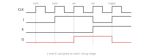
The JK flip-flop has two control inputs, J (set) and K (reset). Unlike the SR latch, it defines the case J = K = 1 as toggle instead of forbidding it.
| J | K | $Q_{next}$ | |
|---|---|---|---|
| 0 | 0 | $Q$ | hold |
| 0 | 1 | 0 | reset |
| 1 | 0 | 1 | set |
| 1 | 1 | $\bar{Q}$ | toggle |
Put $Q_{next}$ on a map with J, K and the present $Q$ as variables and read off the groups:
$$Q_{next} = J\bar{Q} + \bar{K}Q$$
Check the four rows: J = K = 0 gives $Q$; J = 0, K = 1 gives 0; J = 1, K = 0 gives $\bar{Q} + Q = 1$; J = K = 1 gives $\bar{Q}$.
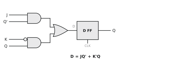
To build one from a D flip-flop, feed it $D = J\bar{Q} + \bar{K}Q$: two AND gates and an OR (Figure 1).
The T flip-flop
The T flip-flop has one input. T = 0 holds, T = 1 toggles:
$$Q_{next} = T \oplus Q$$
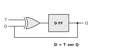
XOR with 0 leaves $Q$ alone and XOR with 1 inverts it. From a D flip-flop it is one XOR gate, $D = T \oplus Q$ (Figure 3).
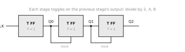
Its natural use is the ripple counter. Chain three T flip-flops with T tied to 1 and clock each one from the previous one’s output (Figure 4). The first toggles on every clock, so its output is the clock divided by two; the second toggles on every edge of that, dividing by four; the third divides by eight. Together the three outputs count 0 to 7 in binary. The word “ripple” refers to the carry passing from stage to stage rather than all stages updating at once, and that causes a timing problem that section 3.5 deals with.
Standard cell libraries and FPGA fabrics provide D flip-flops only; the tool maps JK and T behaviour onto them. The types survive in the 7473 and 7476 of the TTL era, in the schematics that used them, and in the way counters are taught.
Excitation tables
Flip-flop types are converted into one another by putting logic on the inputs, and the systematic tool for that is the excitation table: for each possible transition of $Q$, what inputs are needed.
For a D flip-flop it is trivial, $D = Q_{next}$:
| $Q$ | $Q_{next}$ | D |
|---|---|---|
| 0 | 0 | 0 |
| 0 | 1 | 1 |
| 1 | 0 | 0 |
| 1 | 1 | 1 |
For a JK flip-flop, some inputs are don’t-cares:
| $Q$ | $Q_{next}$ | J | K |
|---|---|---|---|
| 0 | 0 | 0 | X |
| 0 | 1 | 1 | X |
| 1 | 0 | X | 1 |
| 1 | 1 | X | 0 |
To stay at 0 you need J = 0 and K can be anything, since both hold and reset leave 0 at 0. To go from 0 to 1 you need J = 1 and K can be anything, since both set and toggle do it. The other two rows mirror these.
For a T flip-flop, $T = Q \oplus Q_{next}$: toggle exactly when the state has to change.
| Transition | D | J | K | T |
|---|---|---|---|---|
| 0 to 0 | 0 | 0 | X | 0 |
| 0 to 1 | 1 | 1 | X | 1 |
| 1 to 0 | 0 | X | 1 | 1 |
| 1 to 1 | 1 | X | 0 | 0 |
This table is the key to designing sequential circuits by hand: write the state transition table you want, apply the excitation table of the flip-flop you are using to get the required inputs for each row, and minimise those with Karnaugh maps. The don’t-cares in the JK column are what make JK-based designs so compact.
Practice Exercise
Problem 1. A JK flip-flop has $Q = 1$, J = 1, K = 0. What is $Q_{next}$?
Solution
Set, so 1. From the equation: $J\bar{Q} + \bar{K}Q = 1 \cdot 0 + 1 \cdot 1 = 1$.
Problem 2. Make a T flip-flop from a JK flip-flop.
Solution
Connect T to both J and K. Then $Q_{next} = T\bar{Q} + \bar{T}Q = T \oplus Q$. With T = 0 the JK holds, with T = 1 it toggles. No extra gates.
Problem 3. Using the JK excitation table, find the J and K inputs for a 2-bit counter that goes 00, 01, 10, 11, 00.
Solution
| $Q_1$ | $Q_0$ | $Q_1^+$ | $Q_0^+$ | $J_1$ | $K_1$ | $J_0$ | $K_0$ |
|---|---|---|---|---|---|---|---|
| 0 | 0 | 0 | 1 | 0 | X | 1 | X |
| 0 | 1 | 1 | 0 | 1 | X | X | 1 |
| 1 | 0 | 1 | 1 | X | 0 | 1 | X |
| 1 | 1 | 0 | 0 | X | 1 | X | 1 |
Minimising with the don’t-cares: $J_1 = K_1 = Q_0$ and $J_0 = K_0 = 1$. The low bit toggles every cycle and the high bit toggles when the low bit is 1, which is the carry.
We now have the full set of storage elements. The next article is about the numbers that decide whether they work at speed: setup time, hold time and clock-to-Q.