Counters at Work
Every counter type in this section has been built. This last article is about what they are for. Almost everything timed in a digital system, a timeout, a bit period, a PWM cycle, a refresh interval, a frame, is a counter somewhere underneath. Here are five of them.
Dividing a clock
The system clock is 100 MHz and a peripheral wants a 1 MHz tick. A mod-100 counter, seven bits, counts 0 to 99 and a decode of 99 produces a one-cycle pulse:
$$f_{tick} = \frac{f_{clk}}{N} \qquad TICK = (count = N - 1)$$
Do not use that pulse as a clock. Use it as an enable on the peripheral’s flip-flops, which stay on the 100 MHz clock and only do something on the cycles where the tick is high. This keeps the whole design in one clock domain, which is what section 3.2 argued for. Microsecond timers, audio sample rates, blink rates and baud rates all start this way. Where an actual divided clock is needed, for a pin or a slow block that must run at a lower rate, the counter’s top bit or a toggle flip-flop gives a square wave, and it goes through the proper clock network.
PWM
A digital output can only be 0 or 1. To deliver a fraction of the supply to a motor or an LED, switch it fast and control the fraction of time it is on. A free-running counter and a comparator do this (Figure 1):
$$PWM = (count < THRESHOLD)$$
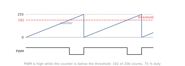
With an 8-bit counter the period is 256 clocks and the duty cycle is $THRESHOLD / 256$ in steps of 0.4 %. A 16-bit counter gives finer steps and a longer period. The threshold is a register that software can write, and the PWM peripheral in any microcontroller is this circuit with a period register and a duty register, sometimes with a prescaler in front of the counter to slow it down. Motor drives run PWM at 20 kHz or more, above hearing; an LED only needs a few hundred hertz before the eye stops seeing flicker; run it above 20 kHz and follow it with an RC filter and you have a crude digital-to-analogue converter.
A stopwatch
A stopwatch showing minutes, seconds and hundredths is a chain of modulo-N counters (Figure 2). A 10 MHz crystal is divided by 100 000 to a 100 Hz tick. The tick enables a mod-100 hundredths counter, whose terminal count enables the seconds units, mod-10, then seconds tens, mod-6, then minutes units and tens. Every stage is on the 10 MHz clock and enabled by the stage below, exactly as in the clock of the modulo-N article.
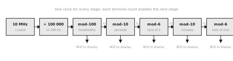
Start and stop is a flip-flop that gates the 100 Hz enable. Reset is a synchronous clear on every stage. A lap function is a register that captures all the digits on a button press while the counters keep running, with the display switched to show the captured value. The accuracy is the crystal’s, typically 20 parts per million, which is about 1.7 seconds a day.
Walking through memory
A DMA controller copies a block of memory without the processor touching each word. At its centre is an address counter: load the start address, and increment it on every completed transfer. A second counter, or a comparator against an end address, says when the block is done. A display controller is the same thing running forever: a pixel counter from 0 to $width \times height - 1$, wrapping at the end of each frame, is the frame buffer read address. At 1920 by 1080 and 60 frames a second it advances about 124 million times a second, which is the pixel clock. More elaborate controllers add a stride, so that a counter can walk down a column of a row-major image, and nested counters for two-dimensional transfers, but they are all counters.
UART timing
A UART sends bits with no clock. Both ends agree on a baud rate, and the receiver has to work out for itself where each bit is. It does this with two counters.
The first makes a tick at 16 times the baud rate. For 115 200 baud from a 100 MHz clock,
$$N = \frac{100,\text{MHz}}{16 \times 115,200} = 54.25$$
Round to 54. The resulting bit rate is $100,\text{MHz} / (16 \times 54) = 115,741$ baud, 0.47 % fast, and a UART frame tolerates about 2 % before the last bit is sampled outside its window. Where the error is too large, a fractional divider alternates between $N$ and $N + 1$ so that the average is right.
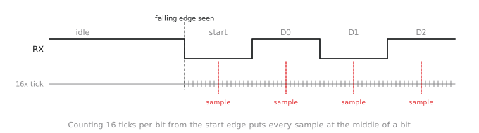
The second counter counts ticks. When the line falls, the start bit has begun. Count 8 ticks and sample: that is the middle of the start bit, and if the line is not low it was noise and the receiver goes back to idle. Then sample every 16 ticks after that, which lands in the middle of each data bit, and finally the stop bit (Figure 3). The tick counter is both the baud generator and the bit-position tracker.
Practice Exercise
Problem 1. Design a PWM generator with 8-bit resolution at 50 kHz from a 100 MHz clock. What prescaler is needed, and what threshold gives 30 % duty?
Solution
A free-running 8-bit counter on 100 MHz gives $100,\text{MHz} / 256 = 390.6,\text{kHz}$. For 50 kHz the counter has to advance at $50,\text{kHz} \times 256 = 12.8,\text{MHz}$, so a prescaler of about 8 ($100 / 8 = 12.5$ MHz, giving 48.8 kHz) or, if exact frequency matters more than exact 8-bit resolution, a mod-2000 counter with no prescaler. For 30 % duty, the threshold is $0.3 \times 256 \approx 77$ with the 8-bit counter, or 600 with the mod-2000 one.
Problem 2. A stopwatch with a 10 MHz reference is to display tenths of a second. What divider produces the 10 Hz tick, and how many flip-flops does it need?
Solution
$10,\text{MHz} / 10,\text{Hz} = 1,000,000$, a mod-1 000 000 counter. $2^{20} = 1,048,576$, so 20 bits, clearing on 999 999. Three cascaded mod-100 counters of 7 bits each do the same with 21 flip-flops and simpler decoding.
Problem 3. Find the baud rate error for 9600 baud from a 50 MHz clock with 16 times oversampling.
Solution
$N = 50,000,000 / (16 \times 9600) = 325.52$. With $N = 326$ the rate is $50,000,000 / 5216 = 9585.9$ baud, 0.15 % slow; with $N = 325$ it is $9615.4$ baud, 0.16 % fast. Either is far inside the 2 % budget.
Counters and registers are made of flip-flops, a few or a few dozen. The last section of this module is about what happens when you need thousands or millions of bits: register files, SRAM, DRAM and ROM.