State Diagrams and State Tables
A state machine can be written down in two ways, as a diagram or as a table. They hold the same information. The diagram is for thinking and for explaining to other people; the table is for deriving the logic. You need both, and the ability to go between them without error, and that is what this article practises.
The diagram
A state diagram is a directed graph. Circles are states, labelled with their names. Arrows are transitions, labelled with the input condition that causes them. For a Moore machine the output is written inside the state circle; for a Mealy machine it is written on the arrow as input / output. The initial state is marked with an arrow from a dot, and reset transitions, if drawn, are dashed.
Labels use the shortest condition that identifies the transition. For inputs A and B, a transition that fires whenever A is 1 is labelled A, not AB + AB’. Several conditions to the same next state are combined with OR.
Every state must have transitions covering every possible input combination. A missing one means the specification is incomplete.
Draw the diagram before you write any Verilog. On paper, on a whiteboard, anywhere. It finds missing transitions and redundant states in minutes, and finding the same error in a waveform takes hours.
The table
A transition table lists $\delta$ and $\lambda$ explicitly, one row per state per input combination, so $|S| \times 2^{|I|}$ rows:
| Current state | Inputs | Next state | Outputs |
|---|
Once the states are encoded, each next-state bit gets a Karnaugh map from the next-state column and each output bit gets one from the output column. The table is the direct source for the logic.
A 1011 detector
A machine that watches a serial input and raises its output when the last four bits were 1011, with overlap allowed: the tail of one match may be the head of the next.
States. Each state records how much of 1011 has been matched so far.
| State | Matched |
|---|---|
| S0 | nothing |
| S1 | 1 |
| S2 | 10 |
| S3 | 101 |
| S4 | 1011, output 1 |
Transitions. For each state and each input, the question is: after this bit, what is the longest tail of what I have received that is also a head of 1011?
From S0: on 0 stay, since 0 starts nothing; on 1 go to S1.
From S1 (have 1): on 0 the tail is 10, go to S2; on 1 the tail is 11, of which only the last 1 matches, stay in S1.
From S2 (have 10): on 0 the tail is 100, nothing matches, back to S0; on 1 the tail is 101, go to S3.
From S3 (have 101): on 0 the tail is 1010, and the longest head of 1011 that ends it is 10, so go to S2, not S0. This is the overlap transition and the one people get wrong. On 1 the tail is 1011, go to S4.
From S4 (have 1011): on 0 the tail is 10110, ending in 10, go to S2; on 1 the tail ends in 1, go to S1. Both are overlap transitions.
Figure 1 is the diagram; it is a Moore machine with the output attached to S4.
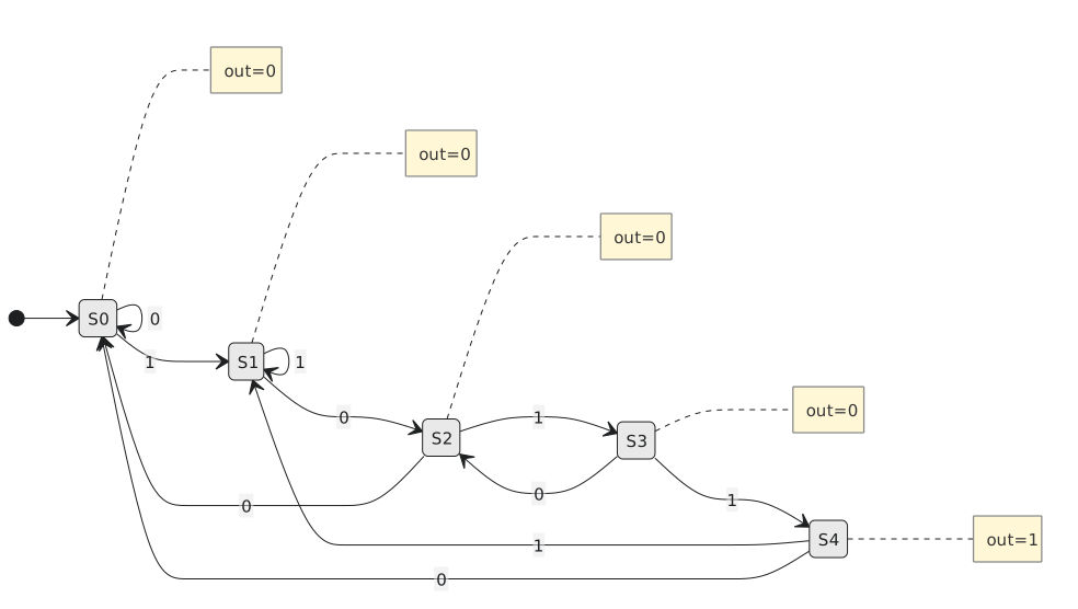
Table.
| State | x | Next | z |
|---|---|---|---|
| S0 | 0 | S0 | 0 |
| S0 | 1 | S1 | 0 |
| S1 | 0 | S2 | 0 |
| S1 | 1 | S1 | 0 |
| S2 | 0 | S0 | 0 |
| S2 | 1 | S3 | 0 |
| S3 | 0 | S2 | 0 |
| S3 | 1 | S4 | 0 |
| S4 | 0 | S2 | 1 |
| S4 | 1 | S1 | 1 |
Five states, two input values, ten rows.
Moore and Mealy notation side by side
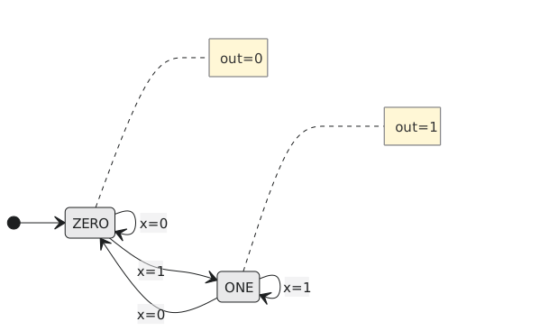
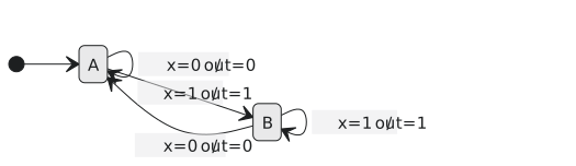
The same trivial machine, one that flags a 1 on its input, drawn both ways: Figure 2 has the output in the state, Figure 3 has it on the arrow.
Mistakes to look for
Missing transitions. Drawing only the interesting arrows leaves the rest undefined; synthesis will do something, but not what you meant. For each state, check that the OR of all its outgoing conditions is true for every input.
Non-determinism. Two arrows out of one state whose conditions overlap. If A = 1 and AB both leave S2, what happens when A = B = 1? Conditions out of a state must be mutually exclusive and exhaustive.
No initial state. Without a reset into a defined state, the behaviour at power-up is undefined.
Unlabelled outputs. Every Moore state and every Mealy transition needs an output. One missing label is one bug in the implementation.
Practice Exercise
Problem 1. Draw a Moore machine that detects three consecutive 1s, with overlap.
Solution
States S0 (none), S1 (one), S2 (two), S3 (three, output 1). On 0 every state returns to S0. On 1: S0 to S1, S1 to S2, S2 to S3, and S3 stays in S3, since another 1 still leaves three consecutive 1s at the tail.
Problem 2. Convert to a table: states A, B (output 0) and C (output 1); A goes to B on 0 and stays on 1; B goes to C on 1 and to A on 0; C goes to A on 0 and to B on 1.
Solution
| State | x | Next | z |
|---|---|---|---|
| A | 0 | B | 0 |
| A | 1 | A | 0 |
| B | 0 | A | 0 |
| B | 1 | C | 0 |
| C | 0 | A | 1 |
| C | 1 | B | 1 |
The output is a property of the current state, so both rows for C have z = 1.
Problem 3. Why does the 1011 detector go from S3 to S2 on a 0 rather than to S0?
Solution
In S3 the last three bits were 101. A 0 makes them 1010. That is not a match, but its last two bits, 10, are the start of 1011, and throwing them away would miss a match in a stream like 1010 11. S2 is the state that means “I have 10”, so that is where to go.
Next: the state names have to become bit patterns in flip-flops, and the choice of pattern changes the circuit more than you might expect.