Synchronous and Asynchronous Design
Section 3.1 gave us the flip-flop. This section is about how to use it, and it starts with the one question every sequential circuit has to answer: when does it change state? There are two answers, and the choice between them shaped the whole semiconductor industry. I want to explain both, and why one of them won so completely.
Synchronous: the clock decides
In a synchronous design a single clock signal is the timekeeper. State changes only at the active clock edge, usually the rising one. Between edges, the combinational logic works out the next state from the inputs and the current state, but nothing captures that result until the edge arrives (Figure 1).
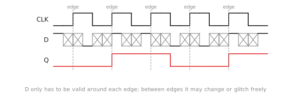
Think of a relay race where the baton may only be passed at the sound of a gun. The runners are always moving, but the handover happens at one instant, for everyone.
Asynchronous: events decide
In an asynchronous design there is no global clock. State changes when an input changes, and the effect ripples through the circuit at whatever speed the gates allow. Blocks coordinate with handshakes: a producer raises a request when its data is ready, the consumer raises an acknowledge when it has taken it, and both drop again (Figure 2). Four transitions per transfer, and no clock anywhere.
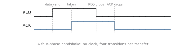
This is a conversation rather than a lecture. The two sides go at whatever pace suits them.
The case for asynchronous
The appeal is real. There is no clock to distribute, and getting one clock to millions of flip-flops with picosecond precision is one of the hardest jobs in chip design. An asynchronous circuit runs at the speed of its actual data, not at the worst-case speed a clock has to be budgeted for. And it burns no power when idle, whereas a clock tree switches every cycle whether or not anything useful is happening, and that is a large fraction of a chip’s dynamic power.
Research groups at Caltech, Manchester and elsewhere built serious asynchronous processors in the 1990s, and the Amulet ARM cores from Manchester ran at noticeably lower power than their clocked equivalents.
Why the industry chose synchronous
And yet almost every commercial digital design is synchronous. The reasons are practical.
Timing analysis is tractable. In a synchronous design, “does this meet timing?” reduces to static timing analysis: find the longest path between any two flip-flops and compare it with the clock period. That runs in minutes on a design with millions of gates. In an asynchronous design, correctness depends on the relative delays of interacting paths, which is a much harder problem and does not scale.
The tools assume it. Synthesis, place and route, timing analysis, formal verification, all of it was built for clocked designs, over decades. Asynchronous tools are research prototypes.
You can debug it. When a synchronous design misbehaves you can stop the clock, read out every register, and see exactly what the circuit knows. An asynchronous circuit has no such frozen instant.
You can test it. Scan-chain testing, the manufacturing test method for every commercial chip, links all the flip-flops into a shift register, loads a state, applies one clock, and shifts the result out. It only works because there is a clock.
At the scale of billions of transistors and thousands of engineers, the synchronous discipline is what makes a design analysable, verifiable and manufacturable. Choosing it is not laziness; it is the judgement that a constrained design that ships beats an optimal one that does not.
Where asynchronous survives
| Area | Approach |
|---|---|
| processor cores, GPUs, DSP datapaths | synchronous |
| memory controllers, PCIe, USB, DDR interfaces | synchronous, with asynchronous crossings between clock domains |
| mixed-signal interfaces | handshakes |
| very-low-power sensor chips | asynchronous wake-up logic |
The asynchronous parts of a commercial chip are the clock domain crossings, where signals pass between unrelated clocks, and a few power-critical corners. The crossings are a major source of silicon bugs, so the small asynchronous part deserves a disproportionate amount of attention, and the last two articles of this section are about it.
The contract
A synchronous design keeps these rules, and Figure 3 shows the structure they imply:
- All state is in flip-flops (or synchronous memories). No transparent latches in the data path, no asynchronous state.
- All flip-flops in a domain share one clock.
- The logic between one flip-flop’s Q and the next one’s D is purely combinational: same inputs, same output, no state of its own.
- There are no combinational feedback loops.
- Nothing changes a flip-flop’s state except the clock edge, with asynchronous reset as the one carefully managed exception.
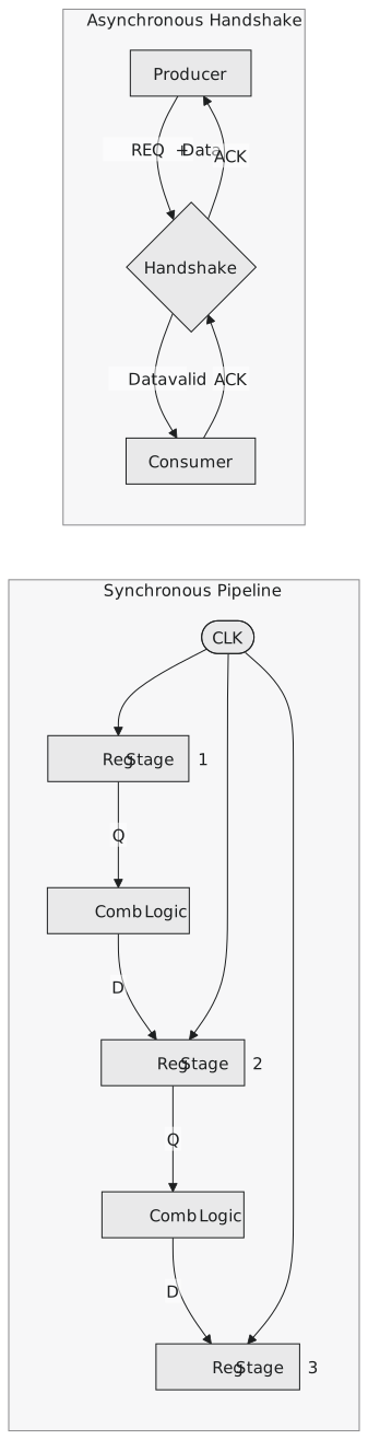
Break the rules and the guarantees go. A combinational loop oscillates at a frequency set by its own delay and corrupts neighbouring state, invisibly in a zero-delay simulation. A latch in the data path opens a window in which timing paths span cycles unpredictably. An unsynchronised input can push a flip-flop into metastability. The next article in this section goes through the rules in detail, and the ones after it through what happens at the boundaries.
Practice Exercise
Problem 1. Synthesis reports a combinational loop through result[3] and carry_chain in an ALU. Is this a violation, and what happens in silicon?
Solution
Yes, rule 4. Bit 3 of the result feeds its own carry logic with no flip-flop in the loop. A zero-delay simulation may settle on some value or print X. In silicon the loop oscillates at a rate set by its delay, and the result register is corrupted on any cycle the ALU is used, intermittently, since the oscillation’s phase against the clock varies. Either the feedback is intended and needs a flip-flop in it, or a signal has been wired to the wrong place.
Problem 2. A team proposes an asynchronous compression accelerator so that it can finish early on easy data. What is the synchronous alternative?
Solution
A variable-latency synchronous block with a done flag: it runs on the clock, detects early completion, raises done, and a controlling state machine gates off further work. It captures most of the energy saving while staying inside the discipline, so timing analysis, synthesis and scan test all work. What it gives up is sub-cycle response: it always waits for the next edge. For most accelerators that is a good trade.
Problem 3. Which of these violates the contract? (a) A flip-flop with a synchronous reset driven by a signal synchronised to the clock. (b) A flip-flop with an asynchronous reset driven straight from a debounced push button. (c) A mux between two combinational paths, selected by a registered signal. (d) An AND gate driving a flip-flop’s clock, with the system clock on one input and a comparator output on the other.
Solution
(a) No. (b) Yes: the reset is released at a random time relative to the clock, and the flip-flop can go metastable on release. It needs a reset synchroniser. (c) No; that is ordinary combinational logic between registers. (d) Yes: a gated clock built from raw logic. The comparator glitches as it settles, and every glitch is a clock edge. Use a clock-gating cell.
The next article is about the clock itself: where it comes from, how it reaches millions of flip-flops, and why skew and jitter eat into the timing budget.