Worked Example: A Vending Machine Controller
The third worked example is the one that breaks the pure state machine approach, and that is the point of it.
Specification
A machine sells one product for 30 cents and accepts nickels, dimes and quarters. When the total reaches 30 cents or more it dispenses and returns any change. A cancel button returns everything inserted.
Inputs, at most one high per cycle: nickel, dime, quarter, cancel.
Outputs: dispense, change_5, change_10, change_15, change_20, return_coin.
The most that can be in the machine before it dispenses is 25 cents, and the largest coin is 25, so the total never exceeds 50 and the change never exceeds 20.
Almost every embedded controller has this shape: inputs accumulate, a threshold triggers an action, and there is always a cancel path.
Approach A: a pure state machine
Every possible total becomes a state. Below the price there are six: S0, S5, S10, S15, S20 and S25. Reaching the price is a dispense state, but a Moore machine needs a different state for each amount of change, since the outputs depend on the state alone. The ways in:
| From | Coin | Total | Change |
|---|---|---|---|
| S5 | quarter | 30 | 0 |
| S20 | dime | 30 | 0 |
| S25 | nickel | 30 | 0 |
| S25 | dime | 35 | 5 |
| S15 | quarter | 40 | 10 |
| S20 | quarter | 45 | 15 |
| S25 | quarter | 50 | 20 |
Five dispense states, DISP_0 to DISP_20, each lasting one cycle and returning to S0. Eleven states in all, four flip-flops (Figure 1).
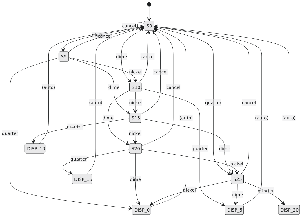
Encode the accumulation states 0000 to 0101 and the dispense states with the top bit set: DISP_0 = 1000, DISP_5 = 1001, DISP_10 = 1010, DISP_15 = 1011, DISP_20 = 1100. Then dispense is simply $Q_3$, and each change output is a decode of the low bits when $Q_3$ is set:
$$\text{change_5} = Q_3 \overline{Q_2},\overline{Q_1} Q_0 \qquad \text{change_10} = Q_3 \overline{Q_2} Q_1 \overline{Q_0}$$
$$\text{change_15} = Q_3 \overline{Q_2} Q_1 Q_0 \qquad \text{change_20} = Q_3 Q_2 \overline{Q_1},\overline{Q_0}$$
That is the output-coded idea from section 3.3.4. return_coin is cancel in any accumulation state, and cancel returns the machine to S0.
Two traces. Dime, nickel, quarter: S10, S15, DISP_10, S0, with dispense and change_10 high for the DISP_10 cycle; 40 cents in, 30 for the product, 10 back. Quarter, quarter: S25, DISP_20, S0; 50 in, 20 back.
It works. Now change the price to 35 cents, or add a second product at 45. The state count grows with every five-cent step of every price, and every change means redrawing the whole diagram. Counting is not what state machines are for.
Approach B: a state machine and a datapath
Separate control from data. The datapath is a 6-bit accumulator register, a mux that selects 5, 10, 25 or 0 according to which coin is present, an adder, and a comparator against 30 (Figure 2). The state machine has three states:
| State | Meaning |
|---|---|
| IDLE | nothing inserted |
| ACCUMULATING | coins inserted, below the price |
| DISPENSING | price reached; dispense and return change |
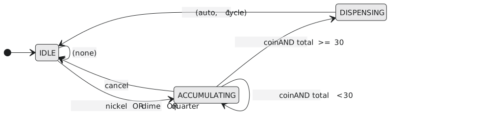
When a coin arrives, the accumulator loads $\text{total} + \text{coin}$. When the comparator says the new total is 30 or more, the machine goes to DISPENSING, where the change is $\text{total} - 30$ from a subtractor and the change outputs are decoded from that. Cancel clears the accumulator and returns to IDLE. The next-state logic of a three-state machine is a few gates.
| Pure FSM | FSM and datapath | |
|---|---|---|
| states | 11 | 3 |
| flip-flops | 4 | 2 for state, 6 for the total |
| next-state logic | four-output function of eight inputs | trivial |
| output logic | decode of the state | subtractor and decoder |
| change the price | redraw the diagram | change one constant |
| add a product | redesign | add a comparator and a mux |
The hybrid uses more flip-flops and less logic, and its real advantage is that it is maintainable. This is how nearly every real controller is built: a small state machine deciding what to do, and registers and arithmetic keeping track of how much.
The three examples together
The traffic light was a pure Moore machine driven by a timer: a cycle with one conditional branch, five states, and outputs that must never glitch. The state tells you everything about what the lamps are doing.
The serial detector was about transitions rather than states: the overlap edges are what make it correct, and the Mealy version showed where a state can be saved.
The vending machine showed where a pure state machine is the wrong tool. Whenever a specification involves counting, accumulating or comparing, split it: a state machine for control and a datapath for the numbers.
The eight-step flow was the same all three times. What changed was the shape of the problem and the right level at which to attack it, and learning to see that before starting is most of what experience in this field consists of.
Practice Exercise
Problem 1. With a 50-cent product and a 50-cent coin added, how many states would approach A need, and what changes in approach B?
Solution
Accumulation states for every total from 0 to 45 in steps of 5, ten of them, plus a dispense state for every possible change amount, which with four coin values now runs from 0 to 45 in steps of 5, potentially ten more. About twenty states and five flip-flops, and a much larger next-state function. In approach B the comparator constant becomes 50, the accumulator grows to 7 bits to hold up to 95, and the state machine is untouched.
Problem 2. Write the next-state logic for the three-state controller with IDLE = 00, ACCUMULATING = 01, DISPENSING = 10.
Solution
Let coin be the OR of the three coin inputs and enough the comparator output. From IDLE a coin goes to ACCUMULATING (or, if a quarter and a nickel make it enough, straight to DISPENSING; with one coin per cycle that cannot happen from zero). From ACCUMULATING, a coin with enough goes to DISPENSING, a coin without stays, cancel goes to IDLE, nothing stays. DISPENSING always returns to IDLE.
$$D_1 = F_0 \cdot \text{coin} \cdot \text{enough}$$
$$D_0 = \overline{F_1},\overline{F_0},\text{coin} + \overline{F_1}, F_0, \overline{\text{cancel}}, \overline{(\text{coin} \cdot \text{enough})}$$
Two flip-flops and a handful of gates, against the four-flip-flop, eight-input function of approach A.
Problem 3. A colleague says approach B “is not really a state machine because it has an adder”. Is that right?
Solution
No. The system’s state is the state register together with the accumulator, up to $4 \times 64$ configurations, and it changes only at clock edges. It is a state machine with a datapath, which is the standard structure of every controller from a vending machine to a processor’s control unit. The three-state controller on its own is a state machine by the formal definition; the datapath is more sequential logic, not something outside the definition.
That completes the state machine section. Section 3.4 turns to registers and shift registers, the blocks that move data around in a synchronous design.