Up/Down, Gray, Johnson and Ring Counters
The binary counter counts up and wraps, and for most jobs that is all you need. This article is about four cases where it is not: counting in both directions, counting so that only one bit changes at a time, and two counters built from a shift register that need almost no decoding.
Up/down
Counting up, bit $i$ toggles when all the bits below it are 1. Counting down, bit $i$ toggles when all the bits below it are 0, because that is when they are about to borrow. With a direction input, 1 for up,
$$T_i = DIR \cdot Q_0 Q_1 \cdots Q_{i-1} + \overline{DIR} \cdot \overline{Q_0},\overline{Q_1} \cdots \overline{Q_{i-1}}$$
For three bits, $T_0 = 1$, $T_1 = DIR \cdot Q_0 + \overline{DIR} \cdot \overline{Q_0}$, which is $Q_0 \odot DIR$, an XNOR, and $T_2 = DIR \cdot Q_0 Q_1 + \overline{DIR} \cdot \overline{Q_0},\overline{Q_1}$.
A complete up/down counter, the 74HC191 for instance, adds enable, parallel load and two terminal-count outputs: carry out when the count is at its maximum and about to wrap up to 0, and borrow out when it is at 0 and about to wrap down. Timer peripherals count down to zero and raise an interrupt; frequency counters count up during a gate time; position counters go both ways.
Gray code
Going from 3 to 4 in binary, 011 to 100, changes three bits. If the three flip-flops are clocked together the change is clean, but if the count is being read by something on another clock, sampled between the edges, that something can see any mixture of old and new bits, 000 or 111 or anything else. A Gray code counter changes exactly one bit per step, including the wrap from the last value to 0:
| Binary | Gray |
|---|---|
| 000 | 000 |
| 001 | 001 |
| 010 | 011 |
| 011 | 010 |
| 100 | 110 |
| 101 | 111 |
| 110 | 101 |
| 111 | 100 |
The easiest way to build one is a binary counter followed by a converter:
$$G_i = B_i \oplus B_{i+1}$$
with $B_N = 0$, so the top bit is unchanged and each lower bit is the XOR of two adjacent binary bits. Three XOR gates for three bits. If the Gray value has to come straight out of flip-flops with no glitches at all, register the converter’s output as well.
This is where the read and write pointers of every asynchronous FIFO come from. The write pointer lives in one clock domain and is sampled in the other through a two-flop synchroniser. With a binary pointer, a sample taken while several bits are changing can be a value that was never written. With a Gray pointer the only possibilities are the old value or the new one, both of which are safe: the FIFO may report full or empty a cycle late, never wrongly.
Johnson counter
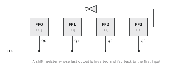
Take a shift register, invert the last output and feed it back to the first input (Figure 1). This is the Johnson counter, or twisted ring counter.
Starting from 0000 the inverted feedback shifts in 1s until the register is full, then 0s until it is empty, so four flip-flops give eight states (Figure 2):
| Step | $Q_3 Q_2 Q_1 Q_0$ |
|---|---|
| 0 | 0000 |
| 1 | 0001 |
| 2 | 0011 |
| 3 | 0111 |
| 4 | 1111 |
| 5 | 1110 |
| 6 | 1100 |
| 7 | 1000 |
| 8 | 0000 |
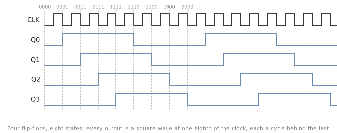
$N$ flip-flops give $2N$ states, and every step changes one bit, so like the Gray counter it never has a multi-bit transition. Each output is a square wave at $1/2N$ of the clock, and the outputs are evenly spaced in phase, which makes it a cheap multiphase clock generator. Decoding is the other attraction. Each state is identified by where the boundary between the 1s and the 0s sits, so every state decodes with a 2-input gate: 0000 is $\overline{Q_0},\overline{Q_3}$, 0001 is $Q_0 \overline{Q_1}$, 0011 is $Q_1 \overline{Q_2}$, 1111 is $Q_3 Q_0$, 1110 is $\overline{Q_0} Q_1$, and so on. A binary counter would need 4-input gates for the same job.
The catch is the states that are not in the sequence. Four flip-flops have 16 states and the counter uses 8. Trace the other 8 with $D_0 = \overline{Q_3}$, $D_1 = Q_0$, $D_2 = Q_1$, $D_3 = Q_2$ and you find they form a loop of their own: 0010, 0101, 1011, 0110, 1101, 1010, 0100, 1001 and back to 0010. If the counter powers up in one of those, or a glitch puts it there, it circulates in that loop forever and never rejoins the real sequence. The fix is a reset into a valid state at start-up. If you want the counter to recover on its own, add a term that detects a pattern which only occurs in the invalid loop, such as a 0 sitting between two 1s, and forces a known state; in practice almost everyone relies on the reset.
Ring counter
Remove the inverter and preload a single 1, and the 1 goes round: 0001, 0010, 0100, 1000. This is the ring counter, $N$ flip-flops for $N$ states, one-hot. It needs no decoding at all, because each output is the indicator for one state. It is exactly the one-hot state machine of section 3.3 with a trivial next-state function, and it is the natural sequencer for anything that steps through phases in a fixed order. It has the same problem with invalid states as the Johnson counter, and needs a reset to put the 1 in.
Choosing
| Counter | States | Flip-flops | Decode | One bit per step |
|---|---|---|---|---|
| Binary | $2^N$ | $N$ | $N$-input | no |
| Gray | $2^N$ | $N$ plus XORs | $N$-input | yes |
| Johnson | $2N$ | $N$ | 2-input | yes |
| Ring | $N$ | $N$ | none | yes |
| Ripple | $2^N$ | $N$ | $N$-input, after settling | no |
Most states per flip-flop, binary. A count that is sampled in another clock domain, Gray. Phase generation or cheap decoding, Johnson. A fixed sequence of steps, ring. Lowest power at low speed with no decoding, ripple.
Practice Exercise
Problem 1. A 3-bit Johnson counter starts at 000. List the sequence and find the states outside it.
Solution
$D_0 = \overline{Q_2}$, $D_1 = Q_0$, $D_2 = Q_1$. Sequence, written $Q_2 Q_1 Q_0$: 000, 001, 011, 111, 110, 100, 000, six states. The other two, 010 and 101, map to each other: from 010, $D_0 = 1$, $D_1 = 0$, $D_2 = 1$, giving 101; from 101, $D_0 = 0$, $D_1 = 1$, $D_2 = 0$, giving 010. A two-state loop the counter cannot leave without a reset.
Problem 2. Write the binary-to-Gray conversion for four bits and give the Gray codes for 0, 7, 8 and 15.
Solution
$G_3 = B_3$, $G_2 = B_3 \oplus B_2$, $G_1 = B_2 \oplus B_1$, $G_0 = B_1 \oplus B_0$.
| Binary | Gray |
|---|---|
| 0000 | 0000 |
| 0111 | 0100 |
| 1000 | 1100 |
| 1111 | 1000 |
7 to 8 changes only $G_3$, and 15 back to 0 changes only $G_3$.
Problem 3. A unipolar stepper motor is driven in half steps with the coil sequence A, AB, B, BC, C, CD, D, DA. Build the sequencer from a Johnson counter and 2-input gates.
Solution
Eight steps, so a 4-bit Johnson counter. Number its states $s_1$ to $s_8$: 0001, 0011, 0111, 1111, 1110, 1100, 1000, 0000. Each coil is on for three consecutive steps, overlapping its neighbours by one: A on $s_8, s_1, s_2$; B on $s_2, s_3, s_4$; C on $s_4, s_5, s_6$; D on $s_6, s_7, s_8$. Each output of the counter is high for four consecutive states, $Q_0$ for $s_1$ to $s_4$, $Q_1$ for $s_2$ to $s_5$, $Q_2$ for $s_3$ to $s_6$, $Q_3$ for $s_4$ to $s_7$, so ANDing two of them, or two complements, picks out a run of three:
$$A = \overline{Q_2},\overline{Q_3} \qquad B = Q_0 Q_1 \qquad C = Q_2 Q_3 \qquad D = \overline{Q_0},\overline{Q_1}$$
Check $s_2 = 0011$: $A = 1$, $B = 1$, $C = 0$, $D = 0$, which is AB. Check $s_8 = 0000$: $A = 1$, $D = 1$, which is DA. Four 2-input gates and no decoder.
That is the counter family. The last article of this section puts them to work: dividing clocks, generating PWM, running a stopwatch, walking through memory and timing a UART.