Moore and Mealy Machines
In the last article the output function $\lambda$ was left slightly vague. The whole difference between the two kinds of state machine is what that one function is allowed to look at.
A Moore machine’s outputs depend only on the state: $\lambda: S \to O$.
A Mealy machine’s outputs depend on the state and the current inputs: $\lambda: S \times I \to O$.
That is all. State count, timing, glitch behaviour and the usual design choice all follow from it.
In hardware
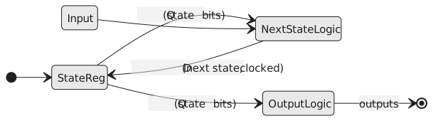
In a Moore machine the output logic sees only the state register (Figure 1). In a Mealy machine it sees the inputs as well, so there is a combinational path straight from the inputs to the outputs (Figure 2).
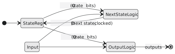
That direct path is both the advantage and the hazard.
An edge detector both ways
We want an output that is high for one cycle each time the input goes from 0 to 1.
A Moore machine has to have a state that means “I have just seen a rising edge”, with the output attached to it (Figure 3). Three states.
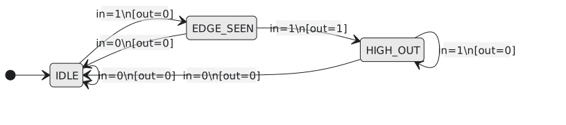
A Mealy machine can produce the pulse on the transition itself (Figure 4). Two states. The arrows are labelled input / output.
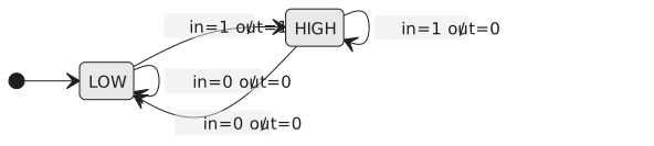
Timing
A Moore output changes only at a clock edge, because it is a function of a registered value. Whatever the input does between edges, the output is steady, and an input glitch cannot become an output glitch.
A Mealy output can change in the middle of a cycle, whenever the input changes. It responds faster, one cycle earlier than a Moore machine for the same event, and it passes input glitches straight through.
State count
For the same job a Mealy machine needs fewer states, because a Moore machine has to have a separate state for every distinct output while a Mealy machine can produce different outputs from one state depending on the input. The saving is usually a state or two, occasionally a flip-flop, and a corresponding simplification of the next-state logic. It is rarely dramatic.
The glitch problem
Suppose an input to a Mealy machine picks up a 2 ns spike from a neighbouring trace. In a Moore machine the spike goes nowhere unless it lands in the setup-hold window of an edge, which is a small target. In a Mealy machine it goes through the output logic and out, and if that output drives a memory enable, a clock enable or anything asynchronous, it does damage.
The registered Mealy machine
The usual answer is to put a register on the Mealy outputs. The output logic is Mealy, the outputs are captured by flip-flops on the same clock, and the outside world sees clean, edge-aligned outputs one cycle later. This keeps Mealy’s state efficiency and gets Moore’s output stability. Most production RTL with “registered outputs” is exactly this, whether or not the designer called it a registered Mealy machine.
Choosing
| Moore | Mealy | Registered Mealy | |
|---|---|---|---|
| output stability | clean, edge-aligned | combinational | clean, edge-aligned |
| state count | more | fewer | fewer |
| output latency | one cycle after entering the state | same cycle as the input | one cycle after the input |
| glitch sensitivity | none | input glitches pass through | none |
| typical use | simple controllers, safe interfaces | protocol parsing | most RTL |
Use Moore when the outputs drive anything that must not glitch. Use plain Mealy when state count is tight and the outputs only feed synchronous logic. Use registered Mealy by default.
A second example: detecting 10
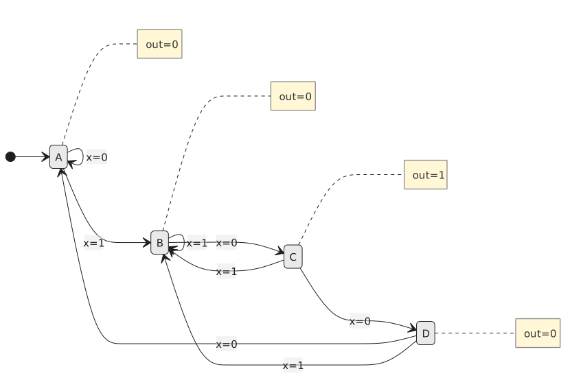
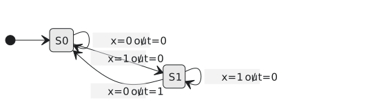
Both machines assert the output for one cycle after seeing 1 then 0. The Moore version has four states (Figure 5), the Mealy version two (Figure 6), and the Mealy output appears a cycle earlier, in the same cycle as the 0 arrives.
Practice Exercise
Problem 1. A Moore machine needs 6 states and the equivalent Mealy machine 4. How many flip-flops does each need with binary encoding?
Solution
$\lceil \log_2 6 \rceil = 3$ and $\lceil \log_2 4 \rceil = 2$. One flip-flop saved, which matters if the machine is replicated many times.
Problem 2. A Mealy output drives the write enable of a synchronous SRAM on the same clock. Is that safe?
Solution
Mostly. The SRAM samples the enable at the clock edge, so a glitch that has settled before the setup window is harmless. A glitch inside the window is not. Registering the output removes the question, at the cost of a cycle.
Problem 3. Turn the two-state Mealy 10 detector into a registered Mealy machine. How much later does the output appear?
Solution
Add a D flip-flop after the output logic. The output logic computes the pulse in the cycle the 0 arrives, the flip-flop captures it at the end of that cycle, and the external output is high during the next cycle: one cycle later than plain Mealy, the same as Moore, with two states instead of four.
The next article is about notation: how to draw a state diagram properly and how to turn it into a table.