Comparators
In the previous articles we selected, decoded and encoded. In this one we compare. Every if in a program ends up as a comparator somewhere in the hardware. When you write if (x > 100) in C, the compiler emits a compare and a conditional branch, and the compare is done by comparator logic in the ALU. The circuit is simple, but it introduces a way of thinking, most significant bit first, that comes back many times in this course.
Equality
Two single bits are equal when both are 0 or both are 1, and the gate that outputs 1 in that case is XNOR:
| $A$ | $B$ | $A = B$ |
|---|---|---|
| 0 | 0 | 1 |
| 0 | 1 | 0 |
| 1 | 0 | 0 |
| 1 | 1 | 1 |
$$EQ = A \odot B = \overline{A \oplus B} = AB + A’B’$$
Two 4-bit numbers are equal when every bit position matches, which is an AND of the bit-wise XNORs:
$$EQ = (A_3 \odot B_3)(A_2 \odot B_2)(A_1 \odot B_1)(A_0 \odot B_0)$$
Four XNOR gates and one 4-input AND. For $n$ bits it is $n$ XNORs and an $n$-input AND, and the delay is two gate levels regardless of $n$. Equality is cheap and fast.
Magnitude
Deciding whether $A > B$ takes more thought. The method is the one you use yourself: compare the most significant digits, and if they differ you are done; if they are equal, move to the next digit, and so on.
For one bit position, three outputs cover the cases (Figure 1):
$$G = AB’ \quad (A > B) \qquad L = A’B \quad (A < B) \qquad E = A \odot B \quad (A = B)$$
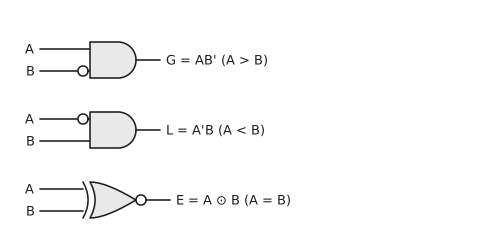
Exactly one of the three is 1 for any input.
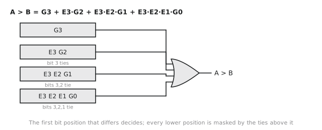
For four bits, compute $G_i$, $L_i$ and $E_i$ for each position $i$, then work from bit 3 downwards. $A > B$ if bit 3 decides it, or bit 3 ties and bit 2 decides it, or bits 3 and 2 tie and bit 1 decides it, or bits 3, 2 and 1 tie and bit 0 decides it:
$$A > B = G_3 + E_3 G_2 + E_3 E_2 G_1 + E_3 E_2 E_1 G_0$$
Figure 2 shows the structure of that expression.
By symmetry
$$A < B = L_3 + E_3 L_2 + E_3 E_2 L_1 + E_3 E_2 E_1 L_0$$
and
$$A = B = E_3 E_2 E_1 E_0$$
The 74HC85 is a 4-bit magnitude comparator in a 16-pin package that implements exactly this. It has eight data inputs, three outputs, and three cascade inputs for building wider comparators. It has been in production since the 1970s, and its datasheet is a good first datasheet to read: short, with a clear function table and timing figures. It is worth ten minutes.
Cascading to 16 bits
The cascade inputs on the 74HC85 exist for building wider comparators. Chain four of them, least significant first, as in Figure 3.

The least significant stage has its cascade inputs tied to “equal” (A=B in, A>B and A<B out). Each stage’s outputs feed the next stage’s cascade inputs. The most significant stage has the final say: if its own four bits decide the comparison, the cascade inputs are irrelevant; if its four bits tie, its outputs simply copy the cascade inputs, which carry the result from the lower stages.
This is a ripple structure, and the worst-case path runs through every stage. For a wide comparator on a critical path, a tree arrangement is faster, and we look at that trade-off again when we build adders in Module 2.
Signed and unsigned
The comparator above is correct for unsigned numbers. For two’s complement numbers everything stays the same except the meaning of the most significant bit, and that one difference causes real bugs.
Unsigned: $A_3 = 1$ and $B_3 = 0$ means $A$ has the larger top bit, so $A > B$.
Signed: $A_3 = 1$ means $A$ is negative and $B_3 = 0$ means $B$ is not, so $A < B$.
So for a signed comparison the top-bit terms swap:
$$G_3^{signed} = A_3’B_3 \qquad L_3^{signed} = A_3B_3’$$
and every lower bit compares exactly as before.
A single comparator does not handle both cases, which is why every processor has separate branch instructions for signed and unsigned comparisons: ARM has BGT and BLT for signed and BHI and BLO for unsigned; x86 has JG and JL against JA and JB; RISC-V has blt and bge against bltu and bgeu. Using the wrong one gives silently wrong answers for negative numbers, and the equivalent mistake in C, comparing a signed and an unsigned variable, is a well-known source of security holes.
Address range checking
An embedded design often needs to answer “is this address in the range 0x8000 to 0xBFFF?” In general that is two comparisons, $A \geq \text{0x8000}$ and $A \leq \text{0xBFFF}$, ANDed together. But look at the constants: 0x8000 is 1000 0000 0000 0000 and 0xBFFF is 1011 1111 1111 1111. Every address in the range has its top two bits equal to 10, and no address outside it does. The whole check is
$$\text{in_range} = A_{15} A_{14}’$$
One AND gate and one inverter. Ranges aligned to powers of two decode this way, and it is why memory maps are laid out on such boundaries.
A 2-bit comparator from the truth table
To see that the MSB-first formula agrees with brute force, here is the 2-bit case with all sixteen rows:
| $A_1$ | $A_0$ | $B_1$ | $B_0$ | GT | EQ | LT |
|---|---|---|---|---|---|---|
| 0 | 0 | 0 | 0 | 0 | 1 | 0 |
| 0 | 0 | 0 | 1 | 0 | 0 | 1 |
| 0 | 0 | 1 | 0 | 0 | 0 | 1 |
| 0 | 0 | 1 | 1 | 0 | 0 | 1 |
| 0 | 1 | 0 | 0 | 1 | 0 | 0 |
| 0 | 1 | 0 | 1 | 0 | 1 | 0 |
| 0 | 1 | 1 | 0 | 0 | 0 | 1 |
| 0 | 1 | 1 | 1 | 0 | 0 | 1 |
| 1 | 0 | 0 | 0 | 1 | 0 | 0 |
| 1 | 0 | 0 | 1 | 1 | 0 | 0 |
| 1 | 0 | 1 | 0 | 0 | 1 | 0 |
| 1 | 0 | 1 | 1 | 0 | 0 | 1 |
| 1 | 1 | 0 | 0 | 1 | 0 | 0 |
| 1 | 1 | 0 | 1 | 1 | 0 | 0 |
| 1 | 1 | 1 | 0 | 1 | 0 | 0 |
| 1 | 1 | 1 | 1 | 0 | 1 | 0 |
The formula gives $GT = A_1B_1’ + (A_1 \odot B_1)A_0B_0’$, $EQ = (A_1 \odot B_1)(A_0 \odot B_0)$ and $LT = A_1’B_1 + (A_1 \odot B_1)A_0’B_0$. Check a few rows against the table and you will find they agree, and a Karnaugh map of the GT column produces the same expression.
Practice Exercise
Problem 1. $A = 1011_2$ and $B = 1010_2$, unsigned. Apply the MSB-first method by hand.
Solution
Bit 3: 1 and 1, tie. Bit 2: 0 and 0, tie. Bit 1: 1 and 1, tie. Bit 0: 1 and 0, so $G_0 = 1$. $A > B = E_3 E_2 E_1 G_0 = 1$. Indeed 11 > 10.
Problem 2. Show that decoding the address range 0x4000 to 0x7FFF on a 16-bit bus needs only two address bits.
Solution
0x4000 is 0100 0000 0000 0000 and 0x7FFF is 0111 1111 1111 1111. Every address in the range has $A_{15} A_{14} = 01$, and the other three quarters of the address space have 00, 10 and 11. So in_range $= A_{15}’ A_{14}$.
Problem 3. Why does comparing the 8-bit two’s complement values 0xFF and 0x01 give $A < B$, when 0xFF is larger than 0x01 as an unsigned number?
Solution
In two’s complement 0xFF is −1 and 0x01 is +1, so −1 < +1 is correct. As unsigned, 255 > 1. The only difference is the interpretation of bit 7: in the signed comparator, $A_7 = 1$ with $B_7 = 0$ means $A$ is negative and therefore smaller; in the unsigned comparator it means $A$ is larger. This is exactly why the two kinds of branch instruction exist.
In the final article of Module 1 we step back and look at how these blocks are combined into larger systems, using a small ALU as the example.