Encoders and Priority Encoders
In the last article a decoder turned a binary code into one active output. In this one we go the other way. In a processor, several peripherals may raise an interrupt in the same clock cycle: a timer expires, a UART finishes a byte, a DMA transfer completes. The processor can service one at a time, and something has to decide which. That something is a priority encoder. The same circuit finds the leading 1 in a floating-point mantissa during normalisation. It looks simple and it does real work.
The plain encoder
A decoder takes $n$ bits and activates one of $2^n$ outputs. An encoder takes $2^n$ inputs, of which exactly one is active, and produces the $n$-bit index of the active input.
For the 4-to-2 encoder, with inputs $I_3$ to $I_0$ and outputs $Y_1 Y_0$:
| $I_3$ | $I_2$ | $I_1$ | $I_0$ | $Y_1$ | $Y_0$ |
|---|---|---|---|---|---|
| 0 | 0 | 0 | 1 | 0 | 0 |
| 0 | 0 | 1 | 0 | 0 | 1 |
| 0 | 1 | 0 | 0 | 1 | 0 |
| 1 | 0 | 0 | 0 | 1 | 1 |
$Y_1$ is 1 when the active input is number 2 or 3, and $Y_0$ is 1 when it is 1 or 3:
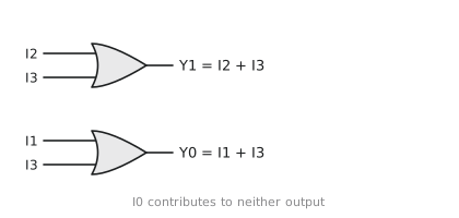
$$Y_1 = I_2 + I_3 \qquad Y_0 = I_1 + I_3$$
Two OR gates (Figure 1). The rule is just binary counting: input $I_k$ contributes to output bit $j$ whenever bit $j$ of $k$ is 1.
What goes wrong
The plain encoder assumes exactly one input is active, and in real systems that assumption fails constantly. Suppose $I_1$ and $I_2$ are both 1:
$$Y_1 = I_2 + I_3 = 1 \qquad Y_0 = I_1 + I_3 = 1$$
The output is 11, which says input 3 is active. Input 3 is not active. The encoder has produced an index that corresponds to nothing.
Interrupt lines from several peripherals can all be asserted at once. Several bus masters can request the bus in the same cycle. The plain encoder handles none of this, which is why you will almost never build one.
The priority encoder
A priority encoder ranks its inputs. When several are active, the output is the index of the highest-ranked one, and the lower-ranked inputs are ignored. It also has a valid output $V$, which is 1 when at least one input is active. Without $V$ you cannot tell “input 0 is active” from “nothing is active”, since both give the output 00.
With $I_3$ as the highest priority:
| $I_3$ | $I_2$ | $I_1$ | $I_0$ | $Y_1$ | $Y_0$ | $V$ |
|---|---|---|---|---|---|---|
| 1 | X | X | X | 1 | 1 | 1 |
| 0 | 1 | X | X | 1 | 0 | 1 |
| 0 | 0 | 1 | X | 0 | 1 | 1 |
| 0 | 0 | 0 | 1 | 0 | 0 | 1 |
| 0 | 0 | 0 | 0 | 0 | 0 | 0 |
The X entries are don’t-cares in the sense of the last section, and they make the logic small.
$Y_1$
$Y_1$ is 1 when $I_3$ is active (whatever the rest do) or when $I_3$ is 0 and $I_2$ is active. That is
$$Y_1 = I_3 + I_3’I_2 = I_3 + I_2$$
by the absorption variant. Priority has not changed $Y_1$ at all, because only inputs 2 and 3 can produce a 1 in the top bit, and either of them beats inputs 0 and 1.
$Y_0$
$Y_0$ is 1 when $I_3$ wins, or when $I_1$ wins, meaning $I_3 = 0$, $I_2 = 0$, $I_1 = 1$. It is 0 when $I_2$ wins or $I_0$ wins. Figure 2 shows the map, with rows $I_3 I_2$ and columns $I_1 I_0$.
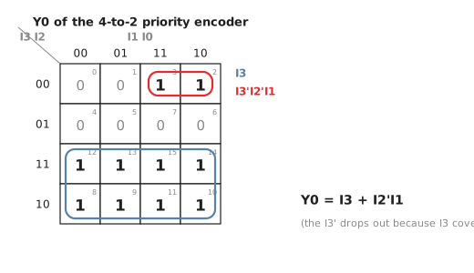
The two rows with $I_3 = 1$ are a group of eight, giving $I_3$. Cells 2 and 3 ($I_3 = 0$, $I_2 = 0$, $I_1 = 1$) are a group of two, giving $I_3’I_2’I_1$. So
$$Y_0 = I_3 + I_3’I_2’I_1 = I_3 + I_2’I_1$$
again by absorption. Check it: with $I_3 = 0, I_2 = 1, I_1 = 1$ we get $0 + 0 = 0$, correct because input 2 wins and its index is 10. With $I_3 = 0, I_2 = 0, I_1 = 1$ we get $0 + 1 = 1$, correct for input 1.
$V$
$V$ is 1 when anything is active:
$$V = I_3 + I_2 + I_1 + I_0$$
All together
$$Y_1 = I_3 + I_2 \qquad Y_0 = I_3 + I_2’I_1 \qquad V = I_3 + I_2 + I_1 + I_0$$
One inverter, one AND, and three OR gates. Priority cost very little over the plain encoder.
An 8-to-3 priority encoder
Two 4-to-2 priority encoders make an 8-to-3, as in Figure 3. The upper encoder handles $I_7$ to $I_4$ and the lower one $I_3$ to $I_0$.
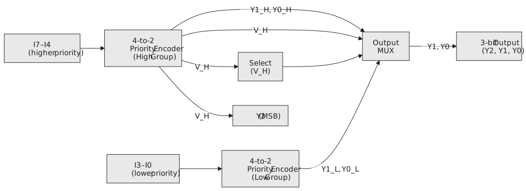
The upper encoder’s valid output $V_H$ says whether any of the high inputs is active. It becomes the top output bit directly, $Y_2 = V_H$, and it drives a mux that picks the low two bits from the upper encoder when $V_H = 1$ and from the lower encoder otherwise. The overall valid is $V = V_H + V_L$. The high group’s valid signal is what enforces the priority between the groups.
Where they are used
Interrupt controllers. The Intel 8259A was essentially an 8-to-3 priority encoder with registers around it. It took eight interrupt request lines, found the highest-priority active one, and presented its index to the processor, which used it to find the service routine. Modern controllers such as ARM’s GIC do the same thing with hundreds of sources.
Floating-point normalisation. After an addition or subtraction the mantissa may no longer have its leading 1 in the top position. Renormalising means finding where the leading 1 is, which is a priority encoder over the mantissa bits with the MSB as highest priority. A leading-zero counter is the same circuit, and it sits on the critical path of a floating-point adder. The CLZ instruction on an ARM Cortex-M is one of these in hardware, and compilers use it for things like $\lfloor \log_2 n \rfloor$.
Bus arbitration. When several bus masters (CPU, DMA, network controller) request the bus, a priority encoder picks the winner and asserts its grant.
Checking the equations
Input $I_3 = 0$, $I_2 = 1$, $I_1 = 1$, $I_0 = 1$. Input 2 should win, so we expect 10 with $V = 1$.
$$Y_1 = 0 + 1 = 1 \qquad Y_0 = 0 + (0)(1) = 0 \qquad V = 1$$
Input $I_3 = 0$, $I_2 = 0$, $I_1 = 1$, $I_0 = 1$. Input 1 should win, expect 01.
$$Y_1 = 0 + 0 = 0 \qquad Y_0 = 0 + (1)(1) = 1 \qquad V = 1$$
Both correct.
Practice Exercise
Problem 1. Design a 4-to-2 priority encoder in which $I_0$ has the highest priority and $I_3$ the lowest.
Solution
| $I_0$ | $I_1$ | $I_2$ | $I_3$ | $Y_1$ | $Y_0$ | $V$ |
|---|---|---|---|---|---|---|
| 1 | X | X | X | 0 | 0 | 1 |
| 0 | 1 | X | X | 0 | 1 | 1 |
| 0 | 0 | 1 | X | 1 | 0 | 1 |
| 0 | 0 | 0 | 1 | 1 | 1 | 1 |
| 0 | 0 | 0 | 0 | 0 | 0 | 0 |
$Y_1$ is 1 when input 2 or 3 wins, both of which need $I_0 = 0$ and $I_1 = 0$: $Y_1 = I_0’I_1’(I_2 + I_3)$.
$Y_0$ is 1 when input 1 wins ($I_0’I_1$) or input 3 wins ($I_0’I_1’I_2’I_3$): $Y_0 = I_0’(I_1 + I_2’I_3)$.
$V = I_0 + I_1 + I_2 + I_3$.
Problem 2. With the standard encoder ($I_3$ highest), what is the output for $I_3 = 1$, $I_2 = 1$, $I_1 = 0$, $I_0 = 0$?
Solution
$Y_1 = 1 + 1 = 1$, $Y_0 = 1 + (0)(0) = 1$, $V = 1$. Output 11, index 3. Input 2 is also active and is ignored.
Problem 3. An 8-input priority encoder with $I_7$ highest receives $I_5 = 1$, $I_3 = 1$, $I_2 = 1$, $I_0 = 1$ and the rest 0. What is the output?
Solution
The highest active input is $I_5$, so the output is 101 with $V = 1$.
In the next article we build the last of the standard blocks, the comparator, which is what every if statement in software eventually becomes.