Boolean Algebra: Two Values, Three Operations
In the first section we learned how hardware represents numbers. In this section we look at how it represents logic, and the tool for that is Boolean algebra. This article introduces the algebra itself: where it came from, the three operations, the truth table, and a worked example. The following articles cover the theorems, De Morgan’s laws, canonical forms and simplification.
Boole and Shannon
In 1847 George Boole, the son of a shoemaker in Lincoln, England, with no university degree and mostly self-taught, published a short book called The Mathematical Analysis of Logic. His idea was that logic, the study of correct reasoning, could be written as algebra. Aristotle had formalised logic two thousand years earlier and philosophers had argued about syllogisms ever since. Boole reduced it to symbols and rules.
His variables took only two values, true and false, which he wrote as 1 and 0. His operations were AND, OR and NOT. Boole died in 1864, and had no idea what his algebra would be used for.
Ninety years later Claude Shannon, a 21-year-old graduate student at MIT, was studying telephone relay networks and noticed that a relay, open or closed, behaves exactly like a Boolean variable. Two relays in series behave like AND. Two in parallel behave like OR. His 1937 master’s thesis, A Symbolic Analysis of Relay and Switching Circuits, showed that any logical function can be built as a circuit of switches. It has been called the most important master’s thesis of the twentieth century, and it is the reason that Boolean algebra is an engineering subject rather than a philosophical one.
Every processor, memory and FPGA is, underneath, a physical implementation of Boole’s algebra. When you write Verilog you are writing something that will be turned into Boolean expressions and then into transistors.
Two values, three operations
Boolean variables can only be 0 or 1. No fractions, no negatives. This matches the physical world of the last section: a voltage is above or below a threshold, a switch is open or closed, a bit is set or cleared.
On these two-valued variables we define three operations.
AND, written $A \cdot B$ or just $AB$. The result is 1 only when both $A = 1$ and $B = 1$. Otherwise it is 0.
OR, written $A + B$. The result is 1 when at least one of $A$ or $B$ is 1. It is 0 only when both are 0.
NOT, written $A’$ or $\bar{A}$. The result is the opposite of $A$.
The $+$ and $\cdot$ symbols are borrowed from ordinary algebra but they are not addition and multiplication. In Boolean algebra $1 + 1 = 1$, because “true OR true” is still true. Beginners write $1 + 1 = 2$ more often than you would think. It helps to read $+$ as “at least one” and $\cdot$ as “all of”.
Why it is called an algebra
Boolean algebra is an algebra, not just a set of rules, because it satisfies a formal set of axioms, known as Huntington’s postulates, much as ordinary algebra does. Some of them look familiar:
| Ordinary algebra | Boolean algebra |
|---|---|
| $a \cdot 1 = a$ | $A \cdot 1 = A$ |
| $a + 0 = a$ | $A + 0 = A$ |
| $a \cdot 0 = 0$ | $A \cdot 0 = 0$ |
| $a + (-a) = 0$ | $A + A’ = 1$ |
| $a(b+c) = ab + ac$ | $A(B+C) = AB + AC$ |
The differences matter more than the similarities. Boolean algebra has a second distributive law that ordinary algebra does not: $A + (B \cdot C) = (A+B) \cdot (A+C)$. It looks wrong the first time you see it. Check it with a truth table and you will find it holds. We go through all the axioms and theorems in the next article.
Switches and relays
Before transistors, logic was built from electromechanical relays. A relay is a switch operated by a coil: current through the coil closes the contacts, and a spring opens them again when the current stops. Relays give a very concrete picture of the three operations, shown in Figure 1.
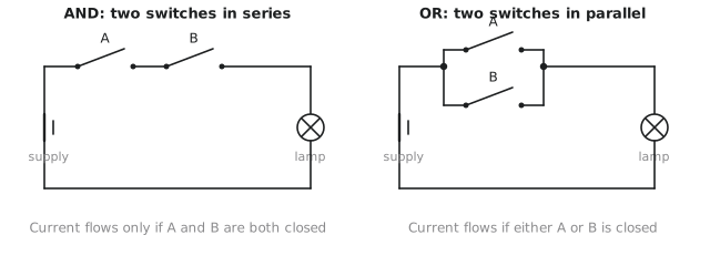
Two switches in series: current flows to the lamp only if switch A AND switch B are both closed. If either is open, the circuit is broken. That is AND.
Two switches in parallel: current flows if switch A OR switch B is closed, or both. Only if both are open does nothing flow. That is OR.
NOT is a relay wired so that energising the coil opens the contacts instead of closing them. Output is always the opposite of the input.
The transistors in a CMOS gate map onto this picture directly. An NMOS transistor is a normally-open switch that closes when its gate is high, and a PMOS transistor is a normally-closed switch that closes when its gate is low. We will build gates out of them in section 1.3.
Truth tables
A truth table lists the output of a Boolean function for every possible combination of its inputs. With $n$ inputs there are exactly $2^n$ rows. The table is not a summary of the function; it is the function, completely specified.
| $A$ | $B$ | $A \cdot B$ | $A + B$ | $A'$ |
|---|---|---|---|---|
| 0 | 0 | 0 | 0 | 1 |
| 0 | 1 | 0 | 1 | 1 |
| 1 | 0 | 0 | 1 | 0 |
| 1 | 1 | 1 | 1 | 0 |
The $A’$ column depends only on $A$, so it really has two rows; AND and OR have two inputs and four rows.
A worked example: the door lock
Suppose a secure door has this rule: it unlocks if the access card is valid AND the PIN is correct, OR if the override key is used.
Name the variables: $C$ for a valid card, $P$ for a correct PIN, $K$ for the override key, and $U$ for the door unlocking. The rule becomes
$$U = (C \cdot P) + K$$
There are three inputs, so $2^3 = 8$ rows:
| Row | $C$ | $P$ | $K$ | $C \cdot P$ | $U = (C \cdot P) + K$ |
|---|---|---|---|---|---|
| 0 | 0 | 0 | 0 | 0 | 0 |
| 1 | 0 | 0 | 1 | 0 | 1 |
| 2 | 0 | 1 | 0 | 0 | 0 |
| 3 | 0 | 1 | 1 | 0 | 1 |
| 4 | 1 | 0 | 0 | 0 | 0 |
| 5 | 1 | 0 | 1 | 0 | 1 |
| 6 | 1 | 1 | 0 | 1 | 1 |
| 7 | 1 | 1 | 1 | 1 | 1 |
Reading a few rows: with no card, no PIN and no key (row 0) the door stays locked. With a valid card and correct PIN and no key (row 6) it unlocks. With an invalid card and wrong PIN but the override key (row 1) it unlocks. Row 5, a valid card, wrong PIN and the key, also unlocks, because the key alone is enough.
The table covers every case, with no ambiguity. A hardware designer can build a circuit from it, and in Verilog it is one line: assign U = (C & P) | K;.
Operator precedence
As in ordinary algebra, there is an order of operations:
- Parentheses
- NOT, which applies to the variable or bracketed group immediately next to it
- AND
- OR
So $A + B \cdot C$ means $A + (B \cdot C)$, not $(A + B) \cdot C$. Verilog follows the same order for & and |, but when in doubt add the parentheses. a | (b & c) costs nothing and saves an argument in a code review.
Practice Exercise
Problem 1. A light is on if switches A and B are both up, or if switch A is up and switch C is down. Write the Boolean expression and build the truth table.
Solution
$L = AB + AC'$
| $A$ | $B$ | $C$ | $AB$ | $C'$ | $AC'$ | $L$ |
|---|---|---|---|---|---|---|
| 0 | 0 | 0 | 0 | 1 | 0 | 0 |
| 0 | 0 | 1 | 0 | 0 | 0 | 0 |
| 0 | 1 | 0 | 0 | 1 | 0 | 0 |
| 0 | 1 | 1 | 0 | 0 | 0 | 0 |
| 1 | 0 | 0 | 0 | 1 | 1 | 1 |
| 1 | 0 | 1 | 0 | 0 | 0 | 0 |
| 1 | 1 | 0 | 1 | 1 | 1 | 1 |
| 1 | 1 | 1 | 1 | 0 | 0 | 1 |
Problem 2. Evaluate $F = A’B + AB’$ for all four input combinations. Which common function is this?
Solution
| $A$ | $B$ | $A'$ | $B'$ | $A’B$ | $AB'$ | $F$ |
|---|---|---|---|---|---|---|
| 0 | 0 | 1 | 1 | 0 | 0 | 0 |
| 0 | 1 | 1 | 0 | 1 | 0 | 1 |
| 1 | 0 | 0 | 1 | 0 | 1 | 1 |
| 1 | 1 | 0 | 0 | 0 | 0 | 0 |
The output is 1 when the inputs differ. This is XOR.
Problem 3. Three people vote. The motion passes if at least two vote yes. Write the expression and the truth table.
Solution
$V = AB + AC + BC$
| $A$ | $B$ | $C$ | $AB$ | $AC$ | $BC$ | $V$ |
|---|---|---|---|---|---|---|
| 0 | 0 | 0 | 0 | 0 | 0 | 0 |
| 0 | 0 | 1 | 0 | 0 | 0 | 0 |
| 0 | 1 | 0 | 0 | 0 | 0 | 0 |
| 0 | 1 | 1 | 0 | 0 | 1 | 1 |
| 1 | 0 | 0 | 0 | 0 | 0 | 0 |
| 1 | 0 | 1 | 0 | 1 | 0 | 1 |
| 1 | 1 | 0 | 1 | 0 | 0 | 1 |
| 1 | 1 | 1 | 1 | 1 | 1 | 1 |
The output is 1 in rows 3, 5, 6 and 7, exactly the rows with two or more yes votes. This is the majority function, and it appears again as the carry output of a full adder.
In the next article we go through the axioms and theorems of Boolean algebra, each of which is a legal move for simplifying an expression, and each of which corresponds to a gate you can remove from a circuit.