Don't-Care Conditions
In the last two articles every cell of the map was a definite 0 or 1. In real designs some input combinations never occur, and for those the output does not matter. This article is about using that freedom. It is the most effective free optimisation a designer has, and it also carries a risk that is worth taking seriously.
What a don’t-care is
A don’t-care condition, marked X or d on a map, is an input combination whose output is irrelevant. There are two kinds.
The first is an input combination that cannot occur. The standard example is binary coded decimal (BCD). Four bits can represent 0 to 15, but a BCD digit is 0 to 9, so the codes 10 to 15 never appear on a correctly working BCD bus. Any logic that decodes BCD can treat those six combinations however it likes.
The second is a valid input whose output nobody reads. A priority encoder with no active input is an example: some designs do not care what the encoded output is in that case, because a separate valid signal says the output is meaningless.
On the map, an X cell may be treated as a 1 or a 0, whichever produces a larger group. You are never obliged to include an X. Include it when it helps a group of 1s grow, and leave it out otherwise. Any X you do not use ends up as a 0 in the circuit you build.
The BCD to seven-segment decoder
This is the classic example, and it is a real one: the 7447 and its relatives were designed exactly this way. A seven-segment display has segments a to g, as in Figure 1. A decoder takes a BCD digit on four inputs and drives the seven segments.
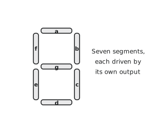
Here I follow the common convention for this circuit and call the input bits D, C, B, A with D the most significant bit.
| Digit | D | C | B | A | a | b | c | d | e | f | g |
|---|---|---|---|---|---|---|---|---|---|---|---|
| 0 | 0 | 0 | 0 | 0 | 1 | 1 | 1 | 1 | 1 | 1 | 0 |
| 1 | 0 | 0 | 0 | 1 | 0 | 1 | 1 | 0 | 0 | 0 | 0 |
| 2 | 0 | 0 | 1 | 0 | 1 | 1 | 0 | 1 | 1 | 0 | 1 |
| 3 | 0 | 0 | 1 | 1 | 1 | 1 | 1 | 1 | 0 | 0 | 1 |
| 4 | 0 | 1 | 0 | 0 | 0 | 1 | 1 | 0 | 0 | 1 | 1 |
| 5 | 0 | 1 | 0 | 1 | 1 | 0 | 1 | 1 | 0 | 1 | 1 |
| 6 | 0 | 1 | 1 | 0 | 1 | 0 | 1 | 1 | 1 | 1 | 1 |
| 7 | 0 | 1 | 1 | 1 | 1 | 1 | 1 | 0 | 0 | 0 | 0 |
| 8 | 1 | 0 | 0 | 0 | 1 | 1 | 1 | 1 | 1 | 1 | 1 |
| 9 | 1 | 0 | 0 | 1 | 1 | 1 | 1 | 1 | 0 | 1 | 1 |
| 10 to 15 | X | X | X | X | X | X | X |
Segment a
Segment a is lit for 0, 2, 3, 5, 6, 7, 8 and 9, and off for 1 and 4. So
$$a = \sum m(0, 2, 3, 5, 6, 7, 8, 9) + d(10, 11, 12, 13, 14, 15)$$
Figure 2 shows the map with the six X cells and the groups I chose.
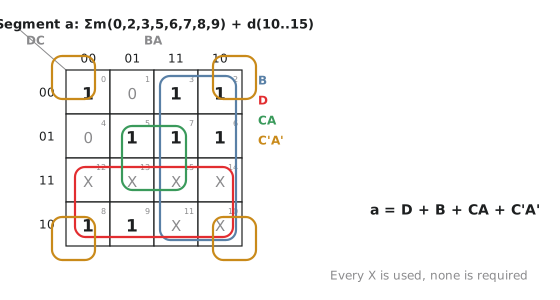
The two right-hand columns, BA = 11 and BA = 10, are all 1 or X, so they form a group of eight with $B = 1$ constant. The bottom two rows, DC = 11 and DC = 10, are all 1 or X, another group of eight with $D = 1$. Cell 5 needs covering. With the X cells at 13 and 15 it joins 7 in a group of four, columns BA = 01 and 11, rows DC = 01 and 11, which has $C = 1$ and $A = 1$ constant: $CA$. And cell 0 needs covering. With 2, 8 and 10 it is the corner group, $C’A’$.
$$a = D + B + CA + C’A’$$
Four terms, six literals. For comparison, Figure 3 shows the same map with the X cells treated as 0. The largest available group is now four, and it takes five terms with fourteen literals to cover the same 1s.
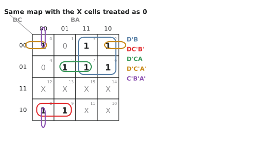
Notice that in the first map every X was used, but none was required to be a 1. If you feed the circuit the code 12, say, segment a will light, because $D = 1$. That is the point of the next section.
The risk
When you use a don’t-care you are asserting that the input will never happen. If the assertion is wrong, even once, the output for that input is whatever the minimiser happened to choose.
It is worth thinking about what “never happens” means in hardware. During power-up, registers are in undefined states for a few nanoseconds before reset takes effect, and an “impossible” BCD code can exist for that long. A bug in the circuit upstream can produce a code from 10 to 15. In aerospace and medical equipment, radiation can flip a bit. A stuck-at fault can hold a node at a fixed value. In each case, a decoder minimised with don’t-cares will do something, and nobody decided what.
For a display decoder that is fine; the worst case is a garbage digit. In a system where wrong behaviour has consequences, you need to decide what should happen for the impossible inputs and design it in, which may mean not using the don’t-cares at all, or adding explicit detection of invalid codes.
There is a second, subtler issue. Minimising with don’t-cares can introduce glitches (static hazards, which we meet in Module 2) on transitions between inputs that the unminimised circuit would not have had. If the output drives something that is sensitive to glitches, a latch enable or an asynchronous input, check the minimised circuit for hazards or minimise without the don’t-cares.
| Situation | Advice |
|---|---|
| BCD display decoder | Use them. Invalid codes really do not occur on a correct BCD path |
| Priority encoder with no active input | Check whether anything ever reads the output in that state before treating it as a don’t-care |
| State machine with unused state codes | Use with care. Give unused states a transition to reset, or use one-hot encoding |
| Safety-critical logic | Avoid, or add explicit invalid-input detection with a defined safe output |
| Prototype | Use freely |
A three-variable example
$F = \sum m(1, 4, 5) + d(2, 3)$. Figure 4 shows the map.
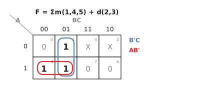
Without the don’t-cares: cells 4 and 5 form a group of two in row A = 1, columns BC = 00 and 01, reading $AB’$. Cell 1 is on its own and reads $A’B’C$. $F = AB’ + A’B’C$, five literals.
With the don’t-cares: cell 1 can pair with cell 5 in column BC = 01, reading $B’C$. Cells 4 and 5 still give $AB’$. $F = AB’ + B’C$, four literals. Could cell 3 help? Cells 1 and 3 would give $A’C$, but cells 1, 3, 5 and 7 would need cell 7, which is 0. So the group of two through cell 5 is the best available. Cells 2 and 3 were not used and become 0 in the circuit.
Practice Exercise
Minimise $F = \sum m(0, 1, 2, 8, 9) + d(10, 11)$, with and without the don’t-cares.
Solution
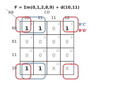
Without the don’t-cares: cells 0, 1, 8 and 9 (rows AB = 00 and 10 through the wrap, columns CD = 00 and 01) form a group of four with $B = 0$ and $C = 0$: $B’C’$. Cell 2 pairs with cell 0 in the top row, reading $A’B’D’$. $F = B’C’ + A’B’D’$, five literals.
With the don’t-cares: cell 10 is now available, so cells 0, 2, 8 and 10 form the corner group $B’D’$, which covers cell 2 with two literals instead of three. $F = B’C’ + B’D’$, four literals. Cell 11 was not needed.
In the last article of this section we look at what happens when the map gets too big to draw, and at the algorithm that synthesis tools use instead.