Antenna Diodes and Jumper Routing: The Two Standard Fixes
In the previous article we saw how a long wire connected only to a gate can damage it during etch. Knowing a net is at risk does not fix it. In this article we look at the two fixes real flows use. Both attack the mechanism directly: one gives the charge somewhere harmless to go, the other makes sure the gate never sees the long wire while it is collecting charge.
Fix one: the antenna diode
An antenna diode is a small diffusion region connected to the at-risk net, close to the gate it protects. In SKY130’s HD library it is the cell sky130_fd_sc_hd__diode_2: an n+ diffusion in the p-substrate, which forms a diode between the net and the substrate. Its only functional pin is DIODE; the power pins are there so it fits in a standard cell row like any other cell.
During fabrication the diode is the harmless path the net was missing. Charge collected on the metal flows through the junction into the substrate, in the forward direction for one polarity and through junction leakage and, if necessary, junction breakdown for the other. A p-n junction conducts at voltages far below what it takes to damage the gate oxide, so the oxide never sees a dangerous field. Figure 1 shows both fixes.
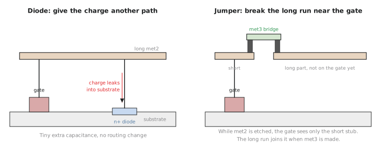
Once the chip is finished and working, the net swings between 0 V and the supply while the substrate sits at 0 V, so the diode is always reverse-biased and does almost nothing. Almost: it adds its junction capacitance to the net, and a little leakage. For a single diode_2 the capacitance is well under a femtofarad, which is small next to the tens of femtofarads of wire on a long net. It starts to matter when a flow sprinkles many diodes on the same small, timing-critical net, or on very sensitive analog nodes.
Because antenna repair usually runs after timing closure, the right habit is simply to include the diodes in the final timing check, which a signoff STA on the final netlist does automatically.
Fix two: jumper routing
The second fix adds no devices. It changes the route. Recall the mechanism: a gate is at risk while a long piece of metal is connected to it and nothing else, during the etch of that layer. If the long run is broken near the gate and the two parts are joined through the layer above, then while the lower layer is etched the gate sees only a short stub. The long part joins the net only when the upper layer is made, and by then the net is also connected to its driver’s output diffusion, which gives the charge a harmless path.
That is a jumper: a short hop up one layer, close to the gate. It adds no junction capacitance, just two vias and a short piece of upper metal. Its cost is routing room. It needs a free track on the layer above at the right spot, and in a congested region, as we saw in Module 6, that track may not be available without moving something else.
Choosing between them
| Antenna diode | Jumper | |
|---|---|---|
| Mechanism | Gives the charge a path through a junction to the substrate | Keeps the long metal off the gate until the net also reaches a diffusion |
| Added capacitance | A small junction capacitance | Essentially none beyond a short piece of wire and two vias |
| Added area | A small cell, which needs a free site near the gate | No cell area, but a track on the layer above |
| Easy to automate | Yes, and dependable | Harder: depends on free routing resources at the right place |
In practice, OpenLane relies mainly on diodes. The router’s layer assignment already avoids many violations, and after global routing OpenROAD’s repair_antennas inserts diodes on the nets that still violate. Some newer OpenROAD versions can also try jumper-style fixes in the global router; check your version’s documentation. Diodes remain the dependable fallback because they can be placed almost anywhere there is a free site.
The balance also shifts with the process node. Thinner gate oxides at smaller nodes reduce the margin between “the junction conducts safely” and “the oxide is damaged”, which makes routing-based prevention relatively more important. The antenna diode article goes into this in more detail.
Hands-on: choose a fix for a real case
A net in the UART’s transmit path runs 400 µm on met2 to the enable pin of a flop that sits on a path with only 60 ps of setup slack at the slow corner. Routing in that region is moderately busy, about 70% utilisation on Module 6’s congestion map, not a hotspot. Which fix would you try first, and why?
Solution
I would try a jumper first. There is routing room (70% is not a hotspot), a jumper adds essentially no capacitance, and the path is tight.
But it is worth being honest about the size of the diode’s cost. 400 µm of met2 carries somewhere around 80 fF of wire capacitance, and one diode_2 adds well under 1 fF, roughly 1% more load. On a stage that takes a few hundred picoseconds that is a few picoseconds at most, which the 60 ps of slack can absorb. So a diode would also be acceptable, and if the jumper could not be routed I would use one without much worry, then confirm the result with the final signoff timing run. The case where the choice really matters is a net with many diodes, or a much smaller net where one diode is a large share of the load.
In the next article we run an antenna check on the routed UART, find a real violation and fix it.