Why a DRC-Clean Layout Can Still Be Functionally Wrong
In Section 8.1 we got the UART’s layout to a clean DRC report. Every shape is wide enough, far enough from its neighbours and properly enclosed. So is the layout correct now?
Not necessarily. A clean DRC report tells you one thing: the fab can build this layout without a width or spacing defect. It says nothing about whether the circuit the layout implements is the circuit you designed. Those are different questions, answered by different tools, and mixing them up is an expensive mistake. In this article we look at the gap between them.
DRC does not know what a net is
As we saw in the last section, a DRC engine looks at raw polygons on layers and measures distances and sizes. It has no idea that one polygon belongs to net baud_tick and another to net tx_shift_reg[3]. It just sees shapes.
That makes it blind to one nasty class of bug: two shapes from two unrelated nets that touch, or merge into one shape, without ever triggering a spacing violation.
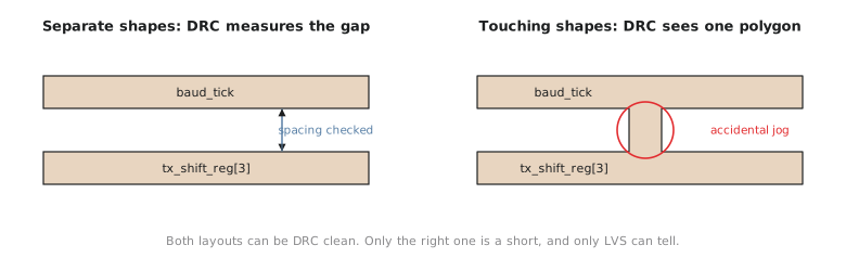
How can that happen when spacing rules exist to keep shapes apart? A spacing rule only fires between two separate shapes. The moment two shapes touch or overlap, the DRC engine sees one larger, perfectly legal polygon. There is no gap left to measure, so the spacing rule has nothing to say. Figure 1 shows the two cases side by side.
A concrete scenario
Picture this in the UART’s layout. The baud-rate generator’s tick net, baud_tick, has a met2 segment running along a cell row. A few tracks over, the transmit data net tx_shift_reg[3] has its own met2 segment running roughly parallel. A jog, whether from a router bug, a bad manual edit or a script that pasted some geometry in the wrong place, joins the two.
baud_tick and tx_shift_reg[3] are now one electrical node. Every baud tick drives a data bit in the transmit shift register, and the two drivers fight each other. That is about as broken as a layout gets, and yet there may be no spacing violation anywhere near the join. Two shapes that were separate became one legal polygon. DRC has nothing to flag, because it never checks whether shapes are supposed to be on the same net, only whether separate shapes are far enough apart.
This is why physical verification has two separate checks and not one. DRC answers “can this layout be manufactured?” LVS answers “does this layout implement the netlist it is supposed to?” Neither covers the other. A layout can fail either one independently, and signoff needs both to pass.
The mistake to avoid is treating a clean DRC report as permission to go to tapeout. A DRC-clean, LVS-dirty layout will fabricate perfectly well into a chip that does not do what you designed. Unlike a small timing miss, a short or an open usually cannot be worked around after fabrication. It has to be caught here.
Hands-on: reason through the blind spot
Before we run any tool, try the reasoning yourself. It is the same reasoning you need to interpret an LVS report in the next two articles.
Two met1 shapes belong to different nets. Shape A’s right edge is at x = 12.500 µm. Shape B’s left edge is also at x = 12.500 µm, over the same y range, so they share an edge.
Does this pair trigger a DRC spacing violation? Would a DRC engine even see two shapes here, or one?
Solution
No spacing violation: there is no gap for a spacing rule to measure. In fact, layout tools merge same-layer shapes that touch into one polygon, the same operation used to combine all the drawn shapes on a layer before checking or writing GDS.
That is the blind spot. Geometrically the tool sees one legal shape where the design intended two separate nets. Nothing in a DRC run can tell “this is deliberately one wide net” from “this is an accidental short between two nets that happen to touch”.
Practice Exercise
A colleague says: “Our layout passed DRC with zero violations, so LVS is basically a formality, we already know the layout is correct.” Write a two-sentence reply based on what each check actually does.
Solution
DRC only checks that the layout’s geometry meets the fab’s manufacturing rules, and it has no notion of which shapes belong to which net, so it cannot detect two nets that touch and merge into one legal shape, or a net that is broken in two. LVS extracts the connectivity the layout really has and compares it with the intended netlist, which is the only way to catch a short, an open or a wrong device that DRC cannot see.
In the next article we run the check that closes this gap: extract a netlist from the routed UART layout and compare it with the design’s netlist using Netgen.