Running an IR Drop Analysis on the UART's Power Grid
In the last two articles we worked IR drop and electromigration by hand on single segments. A real grid has thousands of segments and vias, and current that varies across the die depending on what switches where. Hand calculation does not scale to that. In this article we let OpenROAD solve the UART’s whole grid at once.
Running the analysis
OpenROAD’s power grid analysis, PDNSim, takes the routed power grid, the power drawn by every cell, and the points where the supply enters the grid, and solves the resistive network for the voltage at every node. The per-cell power comes from OpenSTA, so the session needs the libraries, the netlist and the parasitics, just like the signoff STA in Module 7:
openroad
% read_liberty $PDK_ROOT/sky130A/libs.ref/sky130_fd_sc_hd/lib/sky130_fd_sc_hd__tt_025C_1v80.lib
% read_lef $PDK_ROOT/sky130A/libs.ref/sky130_fd_sc_hd/techlef/sky130_fd_sc_hd__nom.tlef
% read_lef $PDK_ROOT/sky130A/libs.ref/sky130_fd_sc_hd/lef/sky130_fd_sc_hd.lef
% read_def runs/uart_full/results/routing/uart_top.eco.def
% read_sdc runs/uart_full/results/routing/uart_top.sdc
% read_spef runs/uart_full/results/extraction/uart_top.nom.eco.spef
% set_propagated_clock [all_clocks]

% set_power_activity -input -activity 0.2
% report_power

% set_pdnsim_net_voltage -net VPWR -voltage 1.8
% analyze_power_grid -net VPWR -outfile vpwr_voltages.rpt \
                     -enable_em -em_outfile vpwr_em.rpt
A few things to understand here:
set_power_activitygives OpenSTA a default switching activity for the inputs, which it propagates through the logic. This is a vectorless estimate. For a sign-off quality answer you would use activity from a simulation of the UART sending and receiving real data.report_powerprints the design’s total power, split into internal, switching and leakage. It is worth a look before the grid analysis, because it tells you how much current the grid has to carry at all.analyze_power_gridsolves the grid forVPWR. Older OpenROAD versions needed a file listing where the supply enters (-vsrc); newer ones place sources on the top grid layer automatically. Check which your version expects.-enable_emalso reports the current in every grid segment and via, for the electromigration check from the previous article.
Run it again with -net VGND for the ground network. Ground bounce is the mirror image of supply drop and needs the same check.
Reading the result
For the UART at 250 MHz, the summary is:
########## IR report #################
Corner: default
Supply voltage          : 1.80e+00 V
Worstcase voltage       : 1.7959e+00 V
Average voltage         : 1.7978e+00 V
Average IR drop         : 2.2e-03 V
Worstcase IR drop       : 4.1e-03 V
######################################
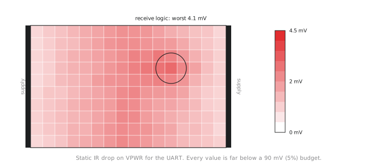
The worst drop anywhere on VPWR is 4.1 mV, about 0.23% of the supply, against a 90 mV (5%) budget. The UART passes with a factor of twenty in hand. Figure 1 shows the drop across the core, drawn from the per-instance voltages the tool wrote to vpwr_voltages.rpt.
Two things about this result are worth understanding, not just accepting.
First, why it is so small. The UART has on the order of a thousand cells and draws in the region of a milliwatt at typical activity, well under a milliamp from a 1.8 V supply, so the grid carries very little current. A power grid sized by OpenLane’s defaults for any reasonable SKY130 design has plenty of metal for that. IR drop becomes a real design problem on large, fast, dense designs, where many thousands of cells switch on the same clock edge.
Second, where the drop is highest. It is largest midway between the straps, as the resistor picture in the first article of this section predicts, and it peaks around the receive logic, which toggles on every sampled bit and so draws more current locally than the idle-looking parts of the design. A uniform current assumption in Module 3 would not have shown this, even though it does not matter at these levels.
The electromigration report for the same run lists the current in every strap segment and via. For the UART the largest currents are a small fraction of a milliamp, far below the limits for the met4 and met5 straps and their via arrays.
If the grid had failed
A clean result does not teach you how to fix a failing one, so let us look at what you would do on a design that reported, say, 110 mV in one region. A single, local violation usually has one of three causes, and it is worth checking which before changing anything:
| Possible cause | How to tell |
|---|---|
| Higher local current than elsewhere | Compare the power of the cells in that region with the design average in the report_power output per instance |
| Sparse grid in that region | Compare the strap and via density there with the rest of the design; did a macro, a blockage or a routing workaround thin the grid locally? |
| A long path from the supply | Check the distance from the region to the nearest strap and to where the supply enters; is it simply the farthest corner? |
The fix follows from the cause. In OpenLane, the grid is controlled by the PDN settings you met in Module 3: the strap pitch (FP_PDN_VPITCH, FP_PDN_HPITCH) and width (FP_PDN_VWIDTH, FP_PDN_HWIDTH). A smaller pitch puts straps closer together, which shortens the path from every cell to a strap and adds more parallel paths; wider straps lower the resistance of each one. For a genuinely local problem, OpenROAD’s PDN generator can also add extra straps over just one region, which avoids spending routing resources across the whole die.
The mistake to avoid is making the whole grid heavier to fix a problem that exists in one corner. That burns routing tracks everywhere, which can create congestion and timing problems of its own, to fix something a local change would have handled.
After any grid change, the flow goes back through routing, extraction, timing and every check in this module, since the change affects all of them.
Practice Exercise
Another design’s IR drop report shows three separate violating regions spread across the die. In each one, only modestly more cells than average are switching, and the strap density is confirmed uniform everywhere. Using the table above, what is the most likely cause, and does it call for a local or a global fix?
Solution
With the grid confirmed uniform (not sparse coverage) and several scattered regions each only moderately busier than average (not a single hotspot), the most likely explanation is that the design as a whole draws more current than the grid was sized for, and the regions that fail are simply the ones slightly busier or farther from the supply.
That calls for a global fix: revisit the Module 3 power planning with the real numbers and reduce the strap pitch or widen the straps across the design. Patching three regions individually would leave the rest of the die only just passing, and it would fail again the next time activity rises anywhere else.
The power grid is verified. In the final section of this module we look at a check that has nothing to do with electrical correctness: fill, added purely because uneven metal density causes a problem during chemical-mechanical polishing.