Density Rule Compliance, Concretely
In the previous article we saw why sparse regions cause trouble in CMP. “Add dummy metal where it is sparse” is the right idea, but a flow needs a precise rule: exactly how sparse is too sparse, and how much fill is enough. In this article we look at how density rules are written and checked.
The rule
A density rule for a metal layer has three parts:
- A window size. The rule is not evaluated over the whole die at once but over a square window, typically tens to a few hundred microns on a side, which is stepped across the whole die.
- A minimum density, the smallest share of the window’s area that must be covered by metal on that layer.
- A maximum density, the largest share allowed.
$$ \text{Density} = \frac{\text{Metal area within the window}}{\text{Window area}} \times 100% $$
A window below the minimum needs dummy fill. A window above the maximum needs the opposite. That is rarer, and it happens where real routing is unusually dense, for example around wide power straps or in a heavily used routing channel. Since you cannot simply remove real wires, the fix there is to change the design in that region: spread the routing, use narrower straps with more of them, or slot wide metal. Figure 1 shows a layer divided into windows.
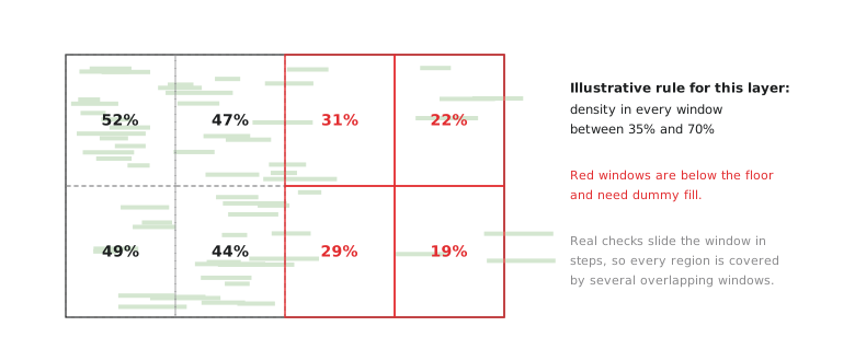
The check steps the window across the die by less than its own width, so every region is covered by several overlapping windows. That catches a sparse patch that would fall between two windows if they were placed side by side.
Why a ceiling as well as a floor
The floor follows directly from the previous article. Too little metal in a window and CMP polishes it down further than its denser neighbours.
The ceiling comes from the same physics in the other direction. Polishing behaviour is not the same all the way from 0% to 100% metal. A window that is nearly all metal behaves differently under the pad from one at a moderate density, just as a sparse one does, because the pad and slurry interact with metal and dielectric differently. Very wide metal shapes also dish in their own middle. The goal of a density rule is not “as much metal as possible”. It is uniformity within a band, and both ends of the band are departures from predictable polishing.
This two-sidedness is common once you trace a rule back to its physics. Wide metal also has its own rules in many processes, such as a maximum width above which a wire must be slotted, for much the same reason.
A worked density calculation
A check window is 100 µm × 100 µm, 10,000 µm². Within it, the real met3 routing, signal wires plus any power strap passing through, covers 2,800 µm².
$$ \text{Density} = \frac{2{,}800}{10{,}000} \times 100% = 28% $$
Against an illustrative range of 35% to 70% (check the SKY130 rule deck for the real values on each layer), 28% is below the floor, so this window needs fill.
$$ \text{Additional metal needed} = (35% - 28%) \times 10{,}000\ \mu m^2 = 700\ \mu m^2 $$
A fill tool does not aim for exactly 35.0%. Like every other rule in this module, it aims somewhat above the floor, so that a small change later does not push the window straight back into violation.
Hands-on: find SKY130’s real density rules
The KLayout decks shipped with the PDK include the density checks. Find where they are and what they say:
grep -ril "density" "$PDK_ROOT/sky130A/libs.tech/klayout/" | head
grep -n -i "density" "$PDK_ROOT/sky130A/libs.tech/klayout/drc/"*.drc | head -30
Density rules are usually defined per layer, because layers differ in thickness and in how sensitive they are to CMP. Check whether the SKY130 deck gives different ranges for different layers, and what window size it uses. Know which is true for this PDK rather than assuming.
Practice Exercise
A 150 µm × 150 µm window on a layer with an illustrative density range of 40% to 65% contains 18,000 µm² of real metal. Is it compliant? If not, how much fill is needed, or, if the problem is at the other end of the range, what does that imply?
Solution
Window area: 150 × 150 = 22,500 µm².
Density: 18,000 / 22,500 × 100% = 80%.
80% is above the 65% maximum. This is a maximum density violation, and fill cannot help; adding metal would make it worse. The real routing or power grid in this window is too dense, and the fix has to come from the design: spread the routing in that region, replace a very wide strap with several narrower ones, or slot the wide metal if the rules allow it. The fill step never touches this kind of violation.
In the next article, the last of this module, we run the fill steps on the UART, check density and the other rules again, and sum up everything the design has now passed.