Module 4: Introduction to Verilog HDL
Three modules of truth tables, maps, gate diagrams and timing diagrams, all done by hand. You can design an ALU and a state machine from a blank sheet. This module is about writing those same circuits down in a form a computer can simulate, synthesise and turn into silicon.
The one thing to get right first
Verilog is not a programming language, and the sooner that sinks in the better. A C program is a list of instructions a processor runs one after another. A Verilog file is a description of hardware: gates, wires, flip-flops and how they are connected. The synthesiser reads it and builds a circuit, and the circuit does not execute anything. It just exists, powered and clocked and permanently wired.
The people who struggle with Verilog are almost always treating it as C with odd syntax. The people who get on with it read every line as a piece of hardware. The first section of this module is mostly about putting that habit in place before you write anything.
What you will write
By the end of the module you will have written and simulated:
- a gate network in structural style, instantiating primitive gates and wiring them up exactly as on a schematic;
- a parameterised N-bit ripple-carry adder in dataflow style, with continuous assignments;
- a 4-to-1 multiplexer in all three modelling styles, so you can see one circuit described three ways;
- a 3-to-8 decoder with enable, with a testbench and a simulation run;
- an eight-operation combinational ALU in behavioural style, as a preview of Module 5.
The sections
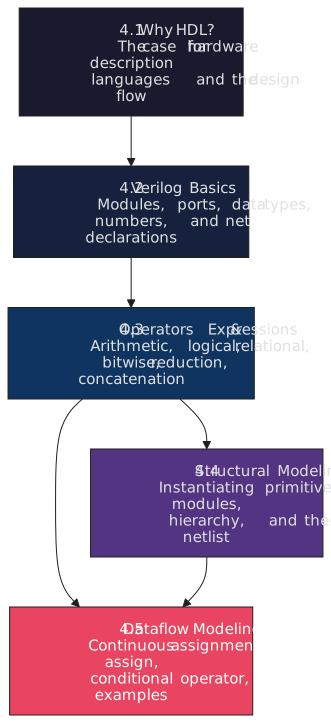
| Section | Topic |
|---|---|
| 4.1 | Why HDL: why the language exists, simulation against synthesis, the flow to silicon, the three languages, and thinking in hardware |
| 4.2 | Verilog basics: modules and ports, wire and reg, vectors and arrays, parameters, literals, directives, style |
| 4.3 | Operators: arithmetic, relational, logical, bitwise, reduction, shift, concatenation, conditional, precedence |
| 4.4 | Structural modelling: primitives, instantiation, port connection, hierarchy, a worked example |
| 4.5 | Dataflow modelling: continuous assignment, operators in practice, conditional dataflow, a worked example, choosing a style |
Section 4.1 is the background. Section 4.2 is the grammar you need for any Verilog at all. Section 4.3 is the operators that go inside expressions, and 4.4 and 4.5 use all of it on the two modelling styles that map most directly to the gates of Modules 1 and 2.
Tools
You need a simulator and a waveform viewer. I use Icarus Verilog and GTKWave, both free, both available on every platform. The commercial simulators, VCS, Xcelium and Questa, cost more than a car each per year; Icarus does not implement every corner of SystemVerilog, but it runs everything in this course.
On macOS with Homebrew:
brew install icarus-verilog
brew install --cask gtkwave
On Ubuntu or Debian:
sudo apt-get install iverilog gtkwave
On Windows, use the installer from bleyer.org/icarus, which includes GTKWave, or use the Ubuntu instructions under WSL2. Check with iverilog -V, which should print a version of 11 or 12.
Every simulation in the course follows the same three steps:
iverilog -o sim tb_module_name.v module_name.v   # compile design and testbench
vvp sim                                          # run; writes the waveform file
gtkwave dump.vcd                                 # look at it
The testbench has to call $dumpfile("dump.vcd") and $dumpvars for the waveform file to appear. If you do not want to install anything, EDA Playground runs Icarus in a browser and has its own waveform viewer.
Conventions
All the Verilog in the course follows these rules:
| Convention | Rule |
|---|---|
| Design file | module_name.v, for example full_adder.v |
| Testbench file | tb_module_name.v |
| First line | `timescale 1ns / 1ps |
| Second line | `default_nettype none |
| Module and port names | snake_case |
| Parameters and constants | UPPER_CASE |
| Comments | // on lines that need explaining, /* */ for the file header |
The `default_nettype none line matters more than it looks. By default, Verilog lets you use a wire you never declared and silently makes it one bit wide. Every typo in a signal name becomes a new one-bit wire, the design compiles, and the bug shows up as an X or a truncated bus in simulation. With the directive, an undeclared name is a compile error. Use it in every file.
Which Verilog
The course teaches Verilog-2001, IEEE 1364-2001. It is what the majority of existing RTL is written in, every tool accepts it, and it added the things that make RTL bearable: always @(*), ANSI port declarations, generate blocks, signed arithmetic and multi-dimensional arrays. SystemVerilog, IEEE 1800, is the modern standard and Module 9 covers the move to it. Its RTL subset is Verilog-2001 with a few additions, so nothing here is wasted.
Before you start
You should be comfortable with Modules 1 to 3: gates, Boolean algebra, maps, the combinational blocks, adders and the ALU, flip-flops, state machines, registers and counters. Verilog is a notation for those things, and if the hardware is not clear the notation will not help.
The first article asks how the industry went from hand-drawn schematics of a few thousand transistors to chips with a hundred billion, and the answer is the reason for everything in this module. Start with section 4.1.