Structural, Dataflow or Behavioural
This is the last article of Module 4. You have written gate primitives, built hierarchies, and described circuits with assign. What is left is the question of which to use when, and the answer is simpler than it looks.
The three styles
| Style | Keywords | Level | For |
|---|---|---|---|
| structural | instances, primitives | gates and blocks | composing verified modules, netlists, library cells |
| dataflow | assign |
RTL | combinational logic that is one expression |
| behavioural | always, initial |
RTL and above | anything with a clock; multi-output or many-case combinational logic |
All three synthesise, apart from initial and delays. All three can live in one module. None is better in general.
Structural
Instantiate when the thing is a module. That covers composition of verified blocks, two 8-bit adders into a 16-bit one:
wire cout_low;

full_adder_8bit u_low  (.a(a[7:0]),  .b(b[7:0]),  .cin(cin),      .sum(sum[7:0]),  .cout(cout_low));
full_adder_8bit u_high (.a(a[15:8]), .b(b[15:8]), .cin(cout_low), .sum(sum[15:8]), .cout(cout));
It also covers the library cells that cannot be inferred: block RAMs, DSP blocks, clock buffers, PLLs, differential pad cells. assign clk = clk_raw; does not make a clock buffer; instantiating the vendor’s buffer cell does:
BUFG u_clk_buf (
    .I(clk_raw),
    .O(clk)
);
And it covers netlists. After synthesis the design is a file of primitive instantiations, and reading, editing or simulating that file is structural work.
Dataflow
assign is the natural form for logic that is one expression:
assign parity   = ^data_byte;
assign zero     = ~|alu_result;
assign eq       = (a == b);
assign y        = sel ? a : b;
assign sign_ext = {{8{narrow[7]}}, narrow};
assign carry    = add_result[WIDTH];
assign overflow = (a[7] == b[7]) && (result[7] != a[7]);
Each is one node on the schematic. It strains when several outputs depend on the same conditions, when a case-style decode passes about eight arms, and it cannot express state at all:
// twelve arms: time for a case statement
assign y = (op == 4'd0)  ? add_result :
           (op == 4'd1)  ? sub_result :
           (op == 4'd2)  ? and_result :
           ...
           (op == 4'd11) ? cmp_result :
                           8'hXX;
Behavioural
An always block is the only way to describe three things. Memory:
always @(posedge clk or negedge rst_n) begin
    if (!rst_n)
        count <= 8'h00;
    else
        count <= count + 1;
end
There is no assign for a flip-flop. Several outputs from one set of conditions:
always @(*) begin
    alu_out  = 8'h00;       // defaults, so that no path leaves an output unassigned
    carry    = 1'b0;
    overflow = 1'b0;

    case (opcode)
        4'h0: begin
            {carry, alu_out} = {1'b0, a} + {1'b0, b};
            overflow = (a[7] == b[7]) && (alu_out[7] != a[7]);
        end
        4'h1: alu_out = a & b;
        // ...
    endcase

    zero     = ~|alu_out;
    negative = alu_out[7];
end
And state machines, which need both. Module 5 is about all three.
They coexist
You do not choose a style for a module. You choose it for each piece of logic:
`timescale 1ns / 1ps
`default_nettype none

module mixed_style_example (
    input  wire [7:0] a,
    input  wire [7:0] b,
    input  wire       clk,
    input  wire       rst_n,
    input  wire       sel,
    output reg  [7:0] result
);

    // dataflow: pick an input
    wire [7:0] mux_out;
    assign mux_out = sel ? a : b;

    // structural: a verified adder
    wire [7:0] add_out;
    wire       cout_unused;

    adder #(.WIDTH(8)) u_add (
        .a   (mux_out),
        .b   (8'h01),
        .cin (1'b0),
        .sum (add_out),
        .cout(cout_unused)
    );

    // behavioural: a register
    always @(posedge clk or negedge rst_n) begin
        if (!rst_n)
            result <= 8'h00;
        else
            result <= add_out;
    end

endmodule
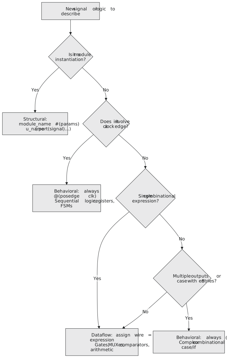
A mux, an incrementer, a register, each in the style that reads best (Figure 1). The decision is quick: a module, instantiate it; a clock edge, always @(posedge clk); one expression, assign; complex combinational logic, always @(*).
Module 4 in review
Why HDL. Text scales where schematics do not; one file is read by a simulator and a synthesiser with different rules; RTL is what both accept; and Verilog is a description of hardware, all of it concurrent, none of it executing.
The grammar. Modules and ANSI ports. wire for anything driven by an assign or an instance, reg for anything driven by a block, and the block, not the keyword, decides what is built. Vectors, part-selects, concatenation and replication. Parameters and $clog2. Sized literals. timescale and default_nettype none at the top of every file.
Operators. Arithmetic and its widths; comparisons and the difference between & and &&; bitwise and reduction; shifts, with >>> on signed operands; the conditional as a mux; parentheses everywhere two kinds of operator meet, and explicit widening wherever a carry matters.
Structural. Primitives, output first. Named port connections, always. Every input connected, one driver per wire. generate for repetition. A thin top level. An ALU as a tree of modules.
Dataflow. assign as a node on the schematic, concurrent and always active. The idioms: carry extraction, sign extension, mux chains, priority encoders, decoders, a table as a conditional chain. Compute everything, select one. A comparator with a proper testbench.
You should now be able to explain why Verilog is not a programming language; say what simulates and what synthesises; pick wire or reg without thinking; write sized literals; use every operator and avoid the precedence and width traps; instantiate with named ports; build a hierarchy; write any single-expression circuit as an assign; write a mux, an encoder and a decoder in dataflow style; and write a testbench with a waveform dump, run it, and read the waveform.
Everything in this module was combinational. The flip-flops, registers, counters and state machines of Module 3 have been waiting. Module 5 is the always block: a flip-flop in four lines, a counter with enable and load in twelve, and state machines as readable, synthesisable code. It is where the blocks of this module become the datapath and the always blocks decide when data moves through it.