Modules and Ports
Section 4.1 was about what Verilog is. This section is the grammar. Open any Verilog file, an IP core, an open-source processor, a first project, and the first thing after the comments is module. Every design, from a two-gate decoder to an SoC, is built from modules, and this article is about what one looks like.
What a module is
A module is a self-contained block of hardware with a named set of connections, its ports, and a body that says how the outputs come from the inputs. It is exactly the box you draw in a block diagram, with labelled signals on its sides. The body can contain three kinds of thing, in any mixture: continuous assignments (assign) for combinational logic written as expressions; procedural blocks (always, initial) for logic written as statements; and instances of other modules, wired together. That last one is how hierarchy works. A 32-bit ALU instantiates four 8-bit slices; a processor top level instantiates the ALU, the register file and the decoder; and at every boundary signals go in through inputs and out through outputs.
The ANSI declaration
Verilog has two syntaxes for a module header. This course uses the ANSI style from Verilog-2001 throughout. Here is a parameterised adder with every part labelled:
`timescale 1ns / 1ps
`default_nettype none

module adder #(
    parameter WIDTH = 8              // parameter with a default
)(
    input  wire [WIDTH-1:0] a,       // direction, type, range, name
    input  wire [WIDTH-1:0] b,
    input  wire             cin,
    output wire [WIDTH-1:0] sum,
    output wire             cout
);

    assign {cout, sum} = a + b + cin;   // WIDTH+1 bits on the left

endmodule
module adder opens the declaration and names it; the file should be adder.v. The #(...) block is the optional parameter list, compile-time constants with defaults that an instantiation can override. The (...) is the port list, and each entry has a direction, a net type, an optional range and a name. endmodule closes it, with no semicolon.
The range [WIDTH-1:0] with the default of 8 is [7:0], eight bits. The pattern [N-1:0] is how nearly all professional code writes an N-bit signal.
Port directions
| Direction | Driven | Read |
|---|---|---|
input |
outside | inside |
output |
inside | outside |
inout |
either | either |
Inputs and outputs are all you need for almost everything. inout is a bidirectional tri-state net, driven by different sources at different times with the others at high impedance: the I²C data line, the data bus of a parallel memory. In FPGA work it appears only at the top level, on the physical pins. If two of your own modules need to exchange data in both directions, give them an input and an output each; using inout to solve a structural problem inside a design is nearly always a mistake.
The 1995 style
Older code, textbooks and IP libraries use the pre-2001 form:
// Verilog-1995 style, for recognition only
module adder (a, b, cin, sum, cout);
    parameter WIDTH = 8;

    input  [WIDTH-1:0] a;
    input  [WIDTH-1:0] b;
    input              cin;
    output [WIDTH-1:0] sum;
    output             cout;

    assign {cout, sum} = a + b + cin;

endmodule
Every port name appears twice, once in the list and once in the declarations, and the two lists drift apart. Add a port to one and forget the other and you get an unhelpful error. Both styles are legal; use the ANSI one.
From block diagram to module
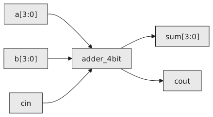
Figure 1 is a 4-bit adder as a box. Every arrow in becomes an input, every arrow out an output, and the widths on the arrows become ranges.
`timescale 1ns / 1ps
`default_nettype none

module adder_4bit (
    input  wire [3:0] a,
    input  wire [3:0] b,
    input  wire       cin,
    output wire [3:0] sum,
    output wire       cout
);

    assign {cout, sum} = a + b + cin;   // 5-bit result

endmodule
Four signals in, two out, and the port list is the diagram. This one-to-one correspondence is one of the good things about the language.
Naming
Module names are lowercase with underscores, adder_4bit, uart_tx, fifo_sync; they start with a letter or underscore, so 4bit_adder is illegal; and they are case-sensitive. The file name matches the module name and there is one module per file, which keeps tools and version control happy. Parameters are UPPER_CASE. Instance names start with u_, which section 4.4 explains.
The single most common syntax error is a missing endmodule. The parser then swallows everything that follows into the current module and reports something confusing many lines away, typically “unexpected keyword module”. When you see that, check that the module above has been closed.
A testbench
To simulate a module you wrap it in another module with no ports, instantiate it, drive its inputs from an initial block and look at its outputs:
`timescale 1ns / 1ps
`default_nettype none

module tb_adder_4bit;

    reg  [3:0] a, b;
    reg        cin;
    wire [3:0] sum;
    wire       cout;

    adder_4bit u_dut (
        .a   (a),
        .b   (b),
        .cin (cin),
        .sum (sum),
        .cout(cout)
    );

    initial begin
        a = 4'd5; b = 4'd3; cin = 1'b0;   // 5 + 3 = 8
        #10;
        a = 4'd9; b = 4'd8; cin = 1'b1;   // 9 + 8 + 1 = 18, carry out
        #10;
        $finish;
    end

endmodule
The .port(signal) form is named port connection. Always use it, never the positional form: it survives reordering of the port list and it documents itself.
Practice Exercise
A comparator takes two inputs of WIDTH bits, default 4, and produces eq, gt and lt. Write the complete module.
Solution
`timescale 1ns / 1ps
`default_nettype none

module comparator #(
    parameter WIDTH = 4
)(
    input  wire [WIDTH-1:0] a,
    input  wire [WIDTH-1:0] b,
    output wire             eq,
    output wire             gt,
    output wire             lt
);

    assign eq = (a == b);
    assign gt = (a >  b);
    assign lt = (a <  b);

endmodule
Exactly one of the three outputs is high at any time, which is a good thing to check in simulation.
That is the shell. The next article is about what goes inside, and starts with the most misunderstood thing in the language: the difference between wire and reg.