From RTL to Silicon
Between the first line of Verilog and a chip coming back from the foundry there are about ten distinct steps, a few dozen tools, and a great deal of verification. You do not need to run all of them to write RTL, but you do need to know they exist, because they explain most of the rules you will be asked to follow. Lint exists because it is cheaper than synthesis. Testbenches have to be thorough because RTL simulation is the cheapest place to find anything. Blocking assignments in a clocked block are dangerous because gate-level simulation will disagree with your RTL simulation a week later.
The flow
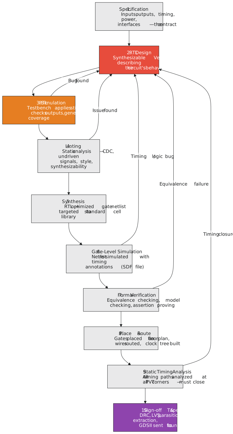
Every arrow back to RTL in Figure 1 is a place a bug can send you to the start again, and the later it fires the more it costs.
Specification
The specification is the contract: what the block computes, its ports and protocols, the clock frequency, the power and area budgets. Without one you cannot know when you are done; with a vague one you will implement the wrong thing exactly. If the specification does not say what happens when two requests arrive together, or what the reset state of every register is, ask before writing anything. Those are not implementation details. They are behaviour, and an assumption made here that contradicts what was wanted is found in silicon.
RTL design
This is the step the course is about. Here is a 4-bit counter that will follow us through the rest of the flow:
`timescale 1ns / 1ps
`default_nettype none

module counter_4bit (
    input  wire       clk,      // system clock
    input  wire       rst_n,    // active-low synchronous reset
    input  wire       en,       // count enable
    output reg  [3:0] count     // current count
);
    always @(posedge clk) begin
        if (!rst_n) begin
            count <= 4'b0000;
        end else if (en) begin
            count <= count + 4'b0001;
        end
        // no assignment when !en: the register holds
    end

endmodule
Every construct here is hardware: the clock edge is the flip-flops’ clock, the reset test is a mux in front of each D input, the addition is a 4-bit incrementer.
RTL simulation
A testbench instantiates the design, drives its inputs and looks at its outputs:
`timescale 1ns / 1ps
`default_nettype none

module tb_counter_4bit;

    reg        clk;
    reg        rst_n;
    reg        en;
    wire [3:0] count;

    counter_4bit dut (
        .clk   (clk),
        .rst_n (rst_n),
        .en    (en),
        .count (count)
    );

    // 10 ns period, 100 MHz
    initial clk = 0;
    always #5 clk = ~clk;

    initial begin
        $dumpfile("counter.vcd");
        $dumpvars(0, tb_counter_4bit);
    end

    initial begin
        rst_n = 0; en = 0;
        @(posedge clk);
        @(posedge clk);           // two cycles of reset

        rst_n = 1; en = 1;
        repeat (20) @(posedge clk);   // count for 20 cycles

        en = 0;
        repeat (5) @(posedge clk);    // check that it holds

        $display("Final count: %0d", count);
        $finish;
    end

endmodule
iverilog -o counter_sim tb_counter_4bit.v counter_4bit.v && vvp counter_sim
gtkwave counter.vcd
In GTKWave, add clk, rst_n, en and count. The count should sit at 0 during reset, climb by one per cycle while enabled, and hold when the enable drops. A bug found here costs an hour: edit, recompile, rerun.
Lint
Lint is static analysis, checking the text without running it. It finds undriven wires, which would be X in simulation and undefined in silicon; signals crossing between clock domains without synchronisers; width mismatches; and non-synthesisable constructs in design files. For open-source work Verilator does a good job:
verilator --lint-only -Wall counter_4bit.v
Commercial linters such as SpyGlass go further, particularly on clock domain crossings. Many teams refuse to merge a change that adds a lint warning.
Synthesis
The synthesiser turns the RTL into a gate netlist. For the counter it will produce four flip-flops, a 4-bit incrementer, and a mux in front of each flip-flop choosing between 0, the incremented value and the held value. With Yosys:
yosys -p "synth -top counter_4bit; write_verilog -noattr synth_counter.v" counter_4bit.v
The commercial equivalents, Design Compiler and Genus, take a target library and timing constraints and report timing and area. Internally the steps are the same: elaborate the RTL into a generic logic network, optimise it, map it to the cells of the target library, and resize or restructure to meet timing.
Gate-level simulation
The netlist is simulated with the same testbench, now with real cell delays from a Standard Delay Format file. This catches functional differences between RTL and netlist, hold violations that only appear with real delays, and X values from uninitialised registers propagating where the RTL model hid them. A bug found here costs about a week, because it has to be traced back through synthesis, fixed in the RTL, resynthesised and rerun.
Formal verification
Equivalence checking proves that the netlist computes the same function as the RTL, for every input, not just the ones the testbench tried. Model checking proves that stated properties hold in every reachable state, and finds counterexamples that a trillion cycles of simulation might miss. Simulation checks the cases you thought of; formal checks the ones you did not. FPGA projects often skip it; automotive, aerospace and medical ASICs cannot.
Place and route
Physical implementation: floorplan the die and place the large macros, plan the power grid, place every standard cell, build a clock tree that delivers the clock to every flip-flop with minimal skew, and route every wire. OpenROAD does this in the open-source world; Innovus and IC Compiler II in the commercial one.
Static timing analysis
Every path in the placed and routed design is checked against setup and hold at every corner of process, voltage and temperature. The design closes timing when every path has positive slack at every corner. A timing failure found here costs about a month, because the fix usually means rethinking the RTL and going through synthesis and placement again.
Sign-off and tape-out
The last checks are physical: design rule checking against the foundry’s manufacturing rules, layout against schematic to confirm the layout implements the netlist, parasitic extraction of the real wire resistance and capacitance, and a final timing run with those parasitics. Then the layout file goes to the foundry. Tape-out was once a reel of magnetic tape; now it is a file transfer, and the name stuck.
A bug found after tape-out means a re-spin: a new mask set, months of calendar time, and a bill that in an advanced process runs to millions.
The cost curve
| Bug found at | Relative cost | Time to fix |
|---|---|---|
| RTL simulation | 1 | hours |
| Lint | 2 | hours to days |
| Gate-level simulation | about 10 | days to weeks |
| Timing analysis | about 30 | weeks to months |
| After tape-out | thousands | months |
This is why RTL verification gets more engineering effort than any other step. If every bug is found in simulation, everything after it is mechanical. On a large SoC the RTL design and verification phase is roughly half the schedule, and the regression farm runs millions of simulations a night.
Where this course sits
Modules 4 and 5 are RTL design, combinational and then sequential. Module 6 is testbenches and simulation. Module 8 introduces synthesis with Yosys and FPGA implementation with the vendor tools. The open-source chain for the whole flow:
| Step | Tool |
|---|---|
| RTL simulation | Icarus Verilog |
| Waveforms | GTKWave |
| Lint | Verilator |
| Synthesis | Yosys with ABC |
| FPGA implementation | Vivado or Quartus |
| ASIC place and route | OpenROAD |
The next article deals with a question everyone asks at this point: Verilog, VHDL or SystemVerilog, and why this course uses Verilog-2001.