Muxes, Encoders and Decoders
The mux, the priority encoder and the decoder are all about selection: a mux picks one of several inputs, an encoder picks the highest active input and names it, a decoder picks one output to raise. All three fall out of the conditional operator, and this article builds each, ending with a circuit you can wire to a display.
Muxes
assign y = sel ? a : b;                       // 2-to-1, eight cells for 8-bit data

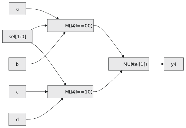
assign y4 = (sel == 2'b00) ? a :              // 4-to-1
            (sel == 2'b01) ? b :
            (sel == 2'b10) ? c :
                             d;

assign y8 = (sel == 3'd0) ? d0 :              // 8-to-1
            (sel == 3'd1) ? d1 :
            (sel == 3'd2) ? d2 :
            (sel == 3'd3) ? d3 :
            (sel == 3'd4) ? d4 :
            (sel == 3'd5) ? d5 :
            (sel == 3'd6) ? d6 : d7;
The chain is priority logic, first true condition wins, and since the conditions on a binary select exclude each other the tool builds a balanced tree (Figure 1). Past 8-to-1, a case in an always block reads better and builds the same thing.
Priority encoder
Order the conditions from highest priority to lowest and the chain does the rest:
`timescale 1ns / 1ps
`default_nettype none

module priority_enc_4to2 (
    input  wire [3:0] req,      // req[3] highest
    output wire [1:0] grant,
    output wire       valid
);
    assign valid = |req;

    assign grant = req[3] ? 2'd3 :
                   req[2] ? 2'd2 :
                   req[1] ? 2'd1 :
                            2'd0;
endmodule
req |
valid |
grant |
|---|---|---|
| 0000 | 0 | 00, meaningless |
| 0001 | 1 | 00 |
| 0010 | 1 | 01 |
| 0101 | 1 | 10 |
| 1111 | 1 | 11 |
valid matters because grant reads 0 both for “request 0” and for “no request”. Eight inputs is the same with seven links and a 3-bit output.
Decoder
A decoder is the inverse: a binary code in, one of $2^N$ lines out. Each output is its minterm ANDed with the enable, which is the map of section 1.5 written down:
`timescale 1ns / 1ps
`default_nettype none

module decoder_2to4 (
    input  wire [1:0] sel,
    input  wire       en,
    output wire [3:0] y      // one-hot, active high
);
    assign y[0] = en & ~sel[1] & ~sel[0];
    assign y[1] = en & ~sel[1] &  sel[0];
    assign y[2] = en &  sel[1] & ~sel[0];
    assign y[3] = en &  sel[1] &  sel[0];
endmodule
Or as one conditional, which scales better when the enable logic grows:
assign y = ~en           ? 4'b0000 :
           (sel == 2'd0) ? 4'b0001 :
           (sel == 2'd1) ? 4'b0010 :
           (sel == 2'd2) ? 4'b0100 :
                           4'b1000;
A seven-segment decoder
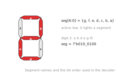
A seven-segment display has segments a to g (Figure 2), and a BCD digit selects which to light. Most boards drive the segments active low: a 0 lights a segment. The output here is ordered {g, f, e, d, c, b, a}, segment a in bit 0.
| Digit | lit | seg[6:0] |
|---|---|---|
| 0 | a b c d e f | 100_0000 |
| 1 | b c | 111_1001 |
| 2 | a b d e g | 010_0100 |
| 3 | a b c d g | 011_0000 |
| 4 | b c f g | 001_1001 |
| 5 | a c d f g | 001_0010 |
| 6 | a c d e f g | 000_0010 |
| 7 | a b c | 111_1000 |
| 8 | all | 000_0000 |
| 9 | a b c d f g | 001_0000 |
`timescale 1ns / 1ps
`default_nettype none

module seg7_decoder (
    input  wire [3:0] bcd,   // 0 to 9
    output wire [6:0] seg    // {g, f, e, d, c, b, a}, active low
);
    //                              gfedcba
    assign seg = (bcd == 4'd0) ? 7'b100_0000 :
                 (bcd == 4'd1) ? 7'b111_1001 :
                 (bcd == 4'd2) ? 7'b010_0100 :
                 (bcd == 4'd3) ? 7'b011_0000 :
                 (bcd == 4'd4) ? 7'b001_1001 :
                 (bcd == 4'd5) ? 7'b001_0010 :
                 (bcd == 4'd6) ? 7'b000_0010 :
                 (bcd == 4'd7) ? 7'b111_1000 :
                 (bcd == 4'd8) ? 7'b000_0000 :
                 (bcd == 4'd9) ? 7'b001_0000 :
                                 7'b111_1111;   // 10 to 15: blank
endmodule
To the synthesiser this is a ten-entry table with four inputs and seven outputs, and on an FPGA it is seven lookup tables, one per segment, which is the ROM-as-logic idea from section 3.6 in miniature. On a board it is a constraint file mapping seg[0] to seg[6] to the segment pins and bcd to four switches; attach it to the BCD counter of section 3.5 and you have a counting display.
A self-checking testbench compares every digit with the table:
`timescale 1ns / 1ps
`default_nettype none

module tb_seg7;
    reg  [3:0] bcd;
    wire [6:0] seg;

    seg7_decoder u_dut (.bcd(bcd), .seg(seg));

    reg [6:0] expected [0:9];
    integer i, errors;

    initial begin
        expected[0] = 7'b100_0000;
        expected[1] = 7'b111_1001;
        expected[2] = 7'b010_0100;
        expected[3] = 7'b011_0000;
        expected[4] = 7'b001_1001;
        expected[5] = 7'b001_0010;
        expected[6] = 7'b000_0010;
        expected[7] = 7'b111_1000;
        expected[8] = 7'b000_0000;
        expected[9] = 7'b001_0000;

        errors = 0;

        for (i = 0; i <= 9; i = i + 1) begin
            bcd = i[3:0]; #10;
            if (seg !== expected[i]) begin
                $display("FAIL digit %0d: got %b, expected %b", i, seg, expected[i]);
                errors = errors + 1;
            end else begin
                $display("PASS digit %0d: seg=%b", i, seg);
            end
        end

        bcd = 4'd10; #10;
        if (seg !== 7'b111_1111) begin
            $display("FAIL invalid BCD: got %b", seg);
            errors = errors + 1;
        end

        if (errors == 0) $display("All tests passed.");
        $finish;
    end
endmodule
iverilog -o seg7_tb tb_seg7.v seg7_decoder.v && vvp seg7_tb
If a digit fails, the usual cause is the bit order: seg[0] is segment a, at the right-hand end of the literal.
Practice Exercise
Add a valid output to the decoder, high for 0 to 9, with one assign. Is a comparison needed, or is there a pattern in the bits?
Solution
assign valid = (bcd <= 4'd9);
is clear and the tool reduces it to a few gates. The pattern, if you want it: 10 to 15 are 1010 to 1111, the values with bit 3 set and bit 2 or bit 1 set, since 8 and 9 have bit 3 set with bits 2 and 1 clear. So
assign valid = ~(bcd[3] & (bcd[2] | bcd[1]));
which is what the comparator becomes after optimisation.
The next article is the section’s worked example: a parameterised comparator taken from specification through testbench, simulation and a look at what synthesis makes of it.