Gate Primitives
This section is structural modelling: describing a circuit by naming its parts and wiring them together, as a schematic does. The smallest parts are the gate primitives built into the language, and they are also what a synthesis tool writes out when it produces a netlist, so being able to read them is a debugging skill as much as a design one.
The primitives
Verilog has AND, OR, NOT, NAND, NOR, XOR and XNOR built in, plus buffers and tri-state drivers. They are instantiated like modules but never declared, and there is one rule that differs from module instantiation: the output comes first, and connections are positional only.
wire a, b, c;
wire y_and, y_or, y_not, y_nand, y_nor, y_xor, y_xnor, y_and3;

and  g_and  (y_and,  a, b);      // y = a & b
or   g_or   (y_or,   a, b);
not  g_not  (y_not,  a);         // one input only
nand g_nand (y_nand, a, b);
nor  g_nor  (y_nor,  a, b);
xor  g_xor  (y_xor,  a, b);
xnor g_xnor (y_xnor, a, b);

and  g_and3 (y_and3, a, b, c);   // any number of inputs
Every primitive except not takes two or more inputs; and g4 (y, a, b, c, d); is a 4-input AND and the tool builds it as a tree if the library has no such cell. not takes exactly one.
The instance name is optional. and (cout, a, b); is legal and you will see it in generated netlists, where compactness matters more than readability. In anything you write, name the instances, because a named instance can be found in a waveform viewer.
Buffers and tri-state drivers
buf    g_buf  (buf_out, a_in);     // y = a; a drive-strength hint
bufif1 g_tri1 (y, data, en);       // y = data when en is 1, z otherwise
bufif0 g_tri0 (y, data, en);       // y = data when en is 0
notif1 g_ni1  (y, data, en);       // inverting, enabled high
notif0 g_ni0  (y, data, en);       // inverting, enabled low
The tri-state primitives drive z when disabled, which is how a shared bus works at the board level. Inside a modern FPGA there are no internal tri-state buses and a floating net is a design error; use these only to model I/O pads.
An SR latch
The cross-coupled NAND latch from section 3.1 is the circuit that structural style suits best, because the code is the schematic:
`timescale 1ns / 1ps
`default_nettype none

module sr_latch (
    input  wire s_n,    // set, active low
    input  wire r_n,    // reset, active low
    output wire q,
    output wire q_n
);
    nand g1 (q,   s_n, q_n);
    nand g2 (q_n, r_n, q);
endmodule
The wiring is circular: q feeds g2 and q_n feeds g1. The simulator handles the loop by re-evaluating until nothing changes, which is exactly the feedback that makes a latch a latch.
| $\overline{S}$ | $\overline{R}$ | $Q$ | $\overline{Q}$ | |
|---|---|---|---|---|
| 1 | 1 | hold | hold | memory |
| 0 | 1 | 1 | 0 | set |
| 1 | 0 | 0 | 1 | reset |
| 0 | 0 | 1 | 1 | forbidden |
A full adder
$$sum = a \oplus b \oplus c_{in} \qquad c_{out} = ab + (a \oplus b), c_{in}$$
`timescale 1ns / 1ps
`default_nettype none

module full_adder_gates (
    input  wire a, b, cin,
    output wire sum, cout
);
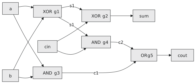
    wire s1;   // a xor b
    wire c1;   // a and b
    wire c2;   // (a xor b) and cin

    xor g1 (s1,   a,  b);
    xor g2 (sum,  s1, cin);
    and g3 (c1,   a,  b);
    and g4 (c2,   s1, cin);
    or  g5 (cout, c1, c2);
endmodule
Five gates, and you can draw the schematic from the code line by line (Figure 1).
Where primitives are used
A primitive maps to one cell of the target library with no interpretation, so a structural description is useful when the circuit has to match a reference schematic exactly, when you are modelling a latch or another feedback structure, in testbench models that need # delays on individual gates, and for learning, because writing a circuit gate by gate makes you think at the level synthesis works at.
Production RTL does not use them for logic. assign sum = a + b; is one line where the gate version of a 16-bit adder is eighty, and the one line gives the tool freedom to choose a faster adder. What you will do with primitives, throughout your career, is read them: a post-synthesis netlist is a file of exactly these instantiations, usually wrapped in library cell names like AND2X1 and NAND2BX2, and an equivalence checker compares your RTL against that file gate by gate.
Practice Exercise
Build a 2-to-1 mux, $y = \overline{sel},a + sel,b$, from primitives.
Solution
`timescale 1ns / 1ps
`default_nettype none

module mux2to1 (
    input  wire a, b,
    input  wire sel,     // 0 selects a, 1 selects b
    output wire y
);
    wire sel_n, and_a, and_b;

    not g_inv  (sel_n, sel);
    and g_and0 (and_a, sel_n, a);
    and g_and1 (and_b, sel,   b);
    or  g_or   (y,     and_a, and_b);
endmodule
With sel at 0, and_a passes a and and_b is 0; with sel at 1 the other way round.
Gates are the atoms. The next article is about the molecules: instantiating modules inside modules, and the port-connection style that makes it safe.