Module Instantiation
The full adder is written and tested on all eight input combinations. A 4-bit adder needs four of them. You could copy the logic four times, which throws away the point of having a module. Instead you instantiate it four times and wire the carries between the copies. That is how hardware scales: one verified block, repeated and connected. It looks like a function call and it is not one, because all four instances exist at once and compute at once.
The syntax
module_type instance_name ( port connections );
full_adder u_fa0 (
    .a   (a_in),
    .b   (b_in),
    .cin (carry_in),
    .sum (sum_out),
    .cout(carry_out)
);
full_adder is the module, u_fa0 is the name of this copy, and each .port(signal) connects a port of the module to a signal in the enclosing one.
Named, not positional
There are two ways to connect ports. Named:
full_adder u_fa_named (
    .a   (operand_a),
    .b   (operand_b),
    .cin (carry_in),
    .sum (partial_sum),
    .cout(carry_out)
);
Positional:
full_adder u_fa_pos (operand_a, operand_b, carry_in, partial_sum, carry_out);
The positional form is shorter and it is a trap. If anyone reorders the port list of full_adder, every positional instantiation is silently miswired; the compiler sees the right number of connections and says nothing. The named form does not care about order and documents itself. Use it always. The same applies to parameters: #(.WIDTH(16)), never #(16).
Parameters at instantiation
adder #(
    .WIDTH(16)
) u_adder_16 (
    .a   (operand_a),
    .b   (operand_b),
    .cin (1'b0),           // a literal on an input port
    .sum (result_wide),
    .cout(carry_flag)
);
The #(...) sits between the module name and the instance name.
What can go on a port
Anything that is a signal-shaped expression. A literal, to tie an input off:
uart_tx u_uart (
    .clk      (sys_clk),
    .rst_n    (reset_n),
    .baud_div (16'd868),     // 100 MHz / 115200
    .data     (tx_data),
    .start    (tx_start),
    .tx_pin   (uart_tx_out)
);
A part-select or a concatenation:
wide_module u_wide (
    .bus_in  ({ctrl_bits, data_byte}),
    .low_byte(data_bus[7:0]),
    .high_out(result_bus[31:16])
);
Size the literals, 16'd868 rather than 868, so that the widths match.
Unused ports
An output you do not need can be given a dummy wire or left explicitly empty:
wire unused_carry;

adder u_adder (
    .a   (op_a),
    .b   (op_b),
    .cin (1'b0),
    .sum (result),
    .cout(unused_carry)   // or .cout()
);
Both are fine, and synthesis removes the logic behind an unused output. An input is different. An input left unconnected floats at z, which becomes x in whatever it feeds, and this is among the harder simulation bugs to find because everything looks connected. Every input gets a signal or a sized constant, no exceptions.
A 4-bit adder
`timescale 1ns / 1ps
`default_nettype none

module rca_4bit_simple (
    input  wire [3:0] a,
    input  wire [3:0] b,
    input  wire       cin,
    output wire [3:0] sum,
    output wire       cout
);
    wire c1, c2, c3;    // the carries between stages

    full_adder u_fa0 (
        .a   (a[0]),
        .b   (b[0]),
        .cin (cin),
        .sum (sum[0]),
        .cout(c1)
    );

    full_adder u_fa1 (
        .a   (a[1]),
        .b   (b[1]),
        .cin (c1),
        .sum (sum[1]),
        .cout(c2)
    );

    full_adder u_fa2 (
        .a   (a[2]),
        .b   (b[2]),
        .cin (c2),
        .sum (sum[2]),
        .cout(c3)
    );

    full_adder u_fa3 (
        .a   (a[3]),
        .b   (b[3]),
        .cin (c3),
        .sum (sum[3]),
        .cout(cout)
    );

endmodule
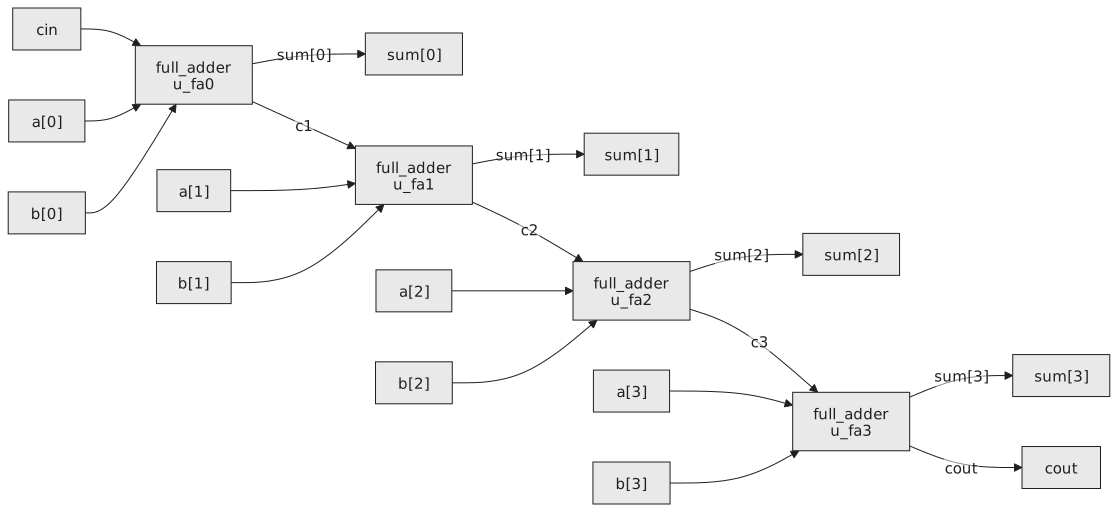
The carry chain is three named wires, and the ripple is visible in the text (Figure 1).
The SystemVerilog shorthand
When a port and the signal connected to it have the same name, SystemVerilog lets you write .a for .a(a), and .* to connect every port that has a same-named signal. It is common in testbenches and top levels written in SystemVerilog and not legal in Verilog-2001; know it so you can read it.
Practice Exercise
A comparator module has a WIDTH parameter defaulting to 4, inputs a and b, and outputs a_gt_b, a_eq_b and a_lt_b. Instantiate it at 8 bits on data_x and data_y, connect only a_gt_b to a wire is_greater, and leave the other outputs explicitly unconnected.
Solution
wire is_greater;

comparator #(
    .WIDTH(8)
) u_cmp (
    .a     (data_x),
    .b     (data_y),
    .a_gt_b(is_greater),
    .a_eq_b(),
    .a_lt_b()
);
Empty parentheses are fine on outputs. On an input they would leave it floating.
The next article goes into the details of port connection: widths that do not match, slicing a wide bus across several instances, and what happens when two outputs drive one wire.