A Parameterised Comparator, Start to Finish
One design, all the way through. The block is a magnitude comparator that answers greater, equal or less for two operands, treating them as signed or unsigned according to a mode input. It is small, and it has enough in it, a parameter, a mode mux, a derived output and a real testbench, to show the whole process.
Specification
Inputs a and b, WIDTH bits, default 8; signed_mode, 1 for two’s complement, 0 for unsigned. Outputs gt, eq, lt. Exactly one output is high at any time.
The mode input exists because 8'hFE is 254 or $-2$ depending on who is asking, and a comparator that does not know which will be wrong half the time.
Architecture
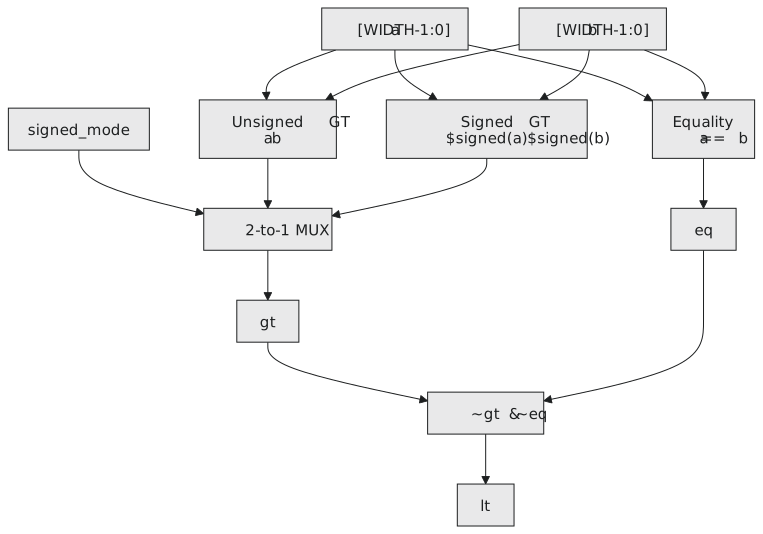
Equality does not depend on the mode; two bit patterns are the same or they are not, and == is an XOR tree.
Greater-than does depend on it. Unsigned > weights the top bit at $+2^{N-1}$; $signed() on both operands weights it at $-2^{N-1}$ and makes the tool build a signed comparator. Compute both and let signed_mode choose (Figure 1).
Less-than is what is left when neither of the others holds:
$$lt = \overline{gt} \cdot \overline{eq}$$
which saves a comparator and makes the one-hot property true by construction.
RTL
`timescale 1ns / 1ps
`default_nettype none

module comparator #(
    parameter WIDTH = 8
)(
    input  wire [WIDTH-1:0] a,
    input  wire [WIDTH-1:0] b,
    input  wire             signed_mode,   // 0 unsigned, 1 two's complement
    output wire             gt,
    output wire             eq,
    output wire             lt
);

    assign eq = (a == b);

    wire gt_unsigned = (a > b);
    wire gt_signed   = ($signed(a) > $signed(b));

    assign gt = signed_mode ? gt_signed : gt_unsigned;

    assign lt = ~gt & ~eq;

endmodule
The two intermediate wires could be folded into one line, assign gt = signed_mode ? ($signed(a) > $signed(b)) : (a > b);, and the hardware would be the same. Naming them makes the two comparators and the mux visible.
One thing not to write is assign lt = !gt;. When a equals b, gt is 0 and that would make lt 1. Equality has to be excluded explicitly.
A directed testbench
The tests that matter are the obvious three cases in each mode, the operands that come out differently in the two modes, the extremes, and the one-hot property after every vector. Two tasks keep it readable:
`timescale 1ns / 1ps
`default_nettype none

module tb_comparator;

    parameter WIDTH = 8;

    reg  [WIDTH-1:0] a, b;
    reg              signed_mode;
    wire             gt, eq, lt;

    comparator #(.WIDTH(WIDTH)) u_dut (
        .a          (a),
        .b          (b),
        .signed_mode(signed_mode),
        .gt         (gt),
        .eq         (eq),
        .lt         (lt)
    );

    task check_invariant;
        input [WIDTH-1:0] a_val, b_val;
        input             s_mode;
        begin
            if ((gt + eq + lt) !== 1)
                $display("INVARIANT VIOLATION: a=%0d b=%0d mode=%b gt=%b eq=%b lt=%b",
                         a_val, b_val, s_mode, gt, eq, lt);
        end
    endtask

    task check;
        input [WIDTH-1:0] a_val, b_val;
        input             s_mode;
        input             exp_gt, exp_eq, exp_lt;
        input [200*8:1]   test_name;
        begin
            if (gt !== exp_gt || eq !== exp_eq || lt !== exp_lt)
                $display("FAIL [%0s]: a=%0d b=%0d mode=%b gt=%b eq=%b lt=%b (expected %b %b %b)",
                         test_name, a_val, b_val, s_mode, gt, eq, lt, exp_gt, exp_eq, exp_lt);
            else
                $display("PASS [%0s]", test_name);
            check_invariant(a_val, b_val, s_mode);
        end
    endtask

    initial begin
        $dumpfile("comparator_waves.vcd");
        $dumpvars(0, tb_comparator);

        $display("=== unsigned ===");
        signed_mode = 1'b0;
        a = 8'd100; b = 8'd50;  #10; check(a, b, signed_mode, 1, 0, 0, "unsigned 100 > 50");
        a = 8'd50;  b = 8'd50;  #10; check(a, b, signed_mode, 0, 1, 0, "unsigned 50 == 50");
        a = 8'd30;  b = 8'd50;  #10; check(a, b, signed_mode, 0, 0, 1, "unsigned 30 < 50");
        a = 8'd0;   b = 8'd0;   #10; check(a, b, signed_mode, 0, 1, 0, "unsigned 0 == 0");
        a = 8'd255; b = 8'd0;   #10; check(a, b, signed_mode, 1, 0, 0, "unsigned 255 > 0");
        a = 8'd0;   b = 8'd255; #10; check(a, b, signed_mode, 0, 0, 1, "unsigned 0 < 255");
        a = 8'hFE;  b = 8'h02;  #10; check(a, b, signed_mode, 1, 0, 0, "unsigned FE > 02");

        $display("=== signed ===");
        signed_mode = 1'b1;
        a = 8'd100; b = 8'd50;  #10; check(a, b, signed_mode, 1, 0, 0, "signed +100 > +50");
        a = 8'd50;  b = 8'd50;  #10; check(a, b, signed_mode, 0, 1, 0, "signed +50 == +50");
        a = 8'hFE;  b = 8'h02;  #10; check(a, b, signed_mode, 0, 0, 1, "signed -2 < +2");
        a = 8'h7F;  b = 8'h80;  #10; check(a, b, signed_mode, 1, 0, 0, "signed +127 > -128");
        a = 8'hFF;  b = 8'hFE;  #10; check(a, b, signed_mode, 1, 0, 0, "signed -1 > -2");
        a = 8'h00;  b = 8'h00;  #10; check(a, b, signed_mode, 0, 1, 0, "signed 0 == 0");

        $display("=== mode switch ===");
        a = 8'hFE; b = 8'h02;
        signed_mode = 1'b0; #10;
        $display("unsigned: a=%h b=%h gt=%b eq=%b lt=%b", a, b, gt, eq, lt);
        signed_mode = 1'b1; #10;
        $display("signed:   a=%h b=%h gt=%b eq=%b lt=%b", a, b, gt, eq, lt);

        $finish;
    end

endmodule
The invariant check adds the three one-bit outputs as integers; the sum is the number that are high, and it has to be exactly 1. It runs after every vector, so a violation cannot slip past. The mode-switch test holds the operands and flips the mode, which is the mux doing its job in front of you.
iverilog -o comparator_sim tb_comparator.v comparator.v
vvp comparator_sim
=== unsigned ===
PASS [unsigned 100 > 50]
PASS [unsigned 50 == 50]
PASS [unsigned 30 < 50]
PASS [unsigned 0 == 0]
PASS [unsigned 255 > 0]
PASS [unsigned 0 < 255]
PASS [unsigned FE > 02]
=== signed ===
PASS [signed +100 > +50]
PASS [signed +50 == +50]
PASS [signed -2 < +2]
PASS [signed +127 > -128]
PASS [signed -1 > -2]
PASS [signed 0 == 0]
=== mode switch ===
unsigned: a=fe b=02 gt=1 eq=0 lt=0
signed:   a=fe b=02 gt=0 eq=0 lt=1
Open the waveform file, gtkwave comparator_waves.vcd, expand tb_comparator in the tree on the left, append a, b, signed_mode, gt, eq and lt, and zoom to fit. Near the end you can see signed_mode rise while the operands hold, and gt fall as lt rises. Get used to the viewer now; from Module 5 on it is where most debugging happens.
A random testbench
The directed tests are the cases you thought of. A second testbench throws random operands at the design and compares it with the simulator’s own operators as a reference model:
`timescale 1ns / 1ps
`default_nettype none

module tb_comparator_random;

    parameter WIDTH   = 8;
    parameter N_TESTS = 200;

    reg  [WIDTH-1:0] a, b;
    reg              signed_mode;
    wire             gt, eq, lt;

    comparator #(.WIDTH(WIDTH)) u_dut (
        .a(a), .b(b), .signed_mode(signed_mode), .gt(gt), .eq(eq), .lt(lt)
    );

    integer i, errors;

    initial begin
        errors = 0;

        signed_mode = 1'b0;
        for (i = 0; i < N_TESTS; i = i + 1) begin
            a = $random; b = $random; #5;
            if (gt !== (a > b) || eq !== (a == b) || lt !== (a < b)) begin
                $display("FAIL unsigned: a=%0d b=%0d gt=%b eq=%b lt=%b", a, b, gt, eq, lt);
                errors = errors + 1;
            end
        end

        signed_mode = 1'b1;
        for (i = 0; i < N_TESTS; i = i + 1) begin
            a = $random; b = $random; #5;
            if (gt !== ($signed(a) > $signed(b)) ||
                eq !== ($signed(a) == $signed(b)) ||
                lt !== ($signed(a) < $signed(b))) begin
                $display("FAIL signed: a=%0d b=%0d gt=%b eq=%b lt=%b", a, b, gt, eq, lt);
                errors = errors + 1;
            end
        end

        if (errors == 0)
            $display("All %0d random tests passed (WIDTH=%0d).", N_TESTS * 2, WIDTH);
        else
            $display("%0d tests FAILED.", errors);

        $finish;
    end

endmodule
A simple reference model beside the real implementation, driven by random stimulus, is the basic pattern of hardware verification, and Module 6 does a great deal more of it.
What synthesis makes
An unsigned comparator, a carry chain on an FPGA; a signed comparator, the same with the top bit handled differently; a one-bit mux between them; an XOR tree and an AND for equality; and a couple of gates for lt. For 8 bits that is around a dozen lookup tables and a critical path of a few nanoseconds through the comparator chain. Set WIDTH to 32 and the tool makes 32-bit comparators; the resource count should grow roughly linearly with the width, and if it jumps at some width, look at whether the timing constraints are pushing the tool off the carry chain.
The cycle
Specify the ports, parameters and invariants. Draw the architecture before writing. Write the RTL. Write directed tests at the boundaries and the mode-dependent cases. Simulate and look at the waveforms. Check what synthesis made of it. It is the same six steps for a comparator and for a processor.
The last article of the module steps back and asks, for any piece of logic, which of the three styles to write it in.