A 4-bit ALU from the Gates Up
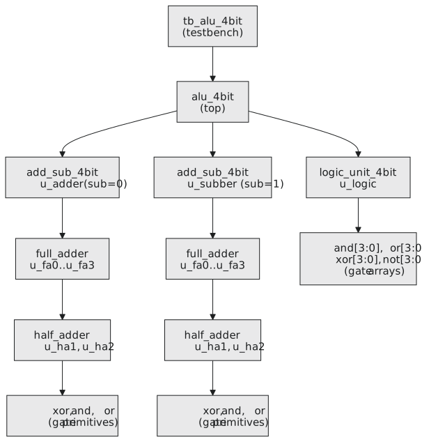
This is the section’s worked example. Primitives, instantiation, port rules and hierarchy all go into one design: the 4-bit ALU of section 2.2, built the way a designer would build it, from the smallest block up, each block tested and then used as a part in the next (Figure 1).
Half adder
$$sum = a \oplus b \qquad c_{out} = ab$$
`timescale 1ns / 1ps
`default_nettype none

module half_adder (
    input  wire a, b,
    output wire sum,
    output wire cout
);
    xor g_xor (sum,  a, b);
    and g_and (cout, a, b);
endmodule
Two gates, four test vectors, and after that it is a black box.
Full adder
Two half adders and an OR: add $a$ and $b$, then add the carry-in to the result.
`timescale 1ns / 1ps
`default_nettype none

module full_adder (
    input  wire a, b, cin,
    output wire sum,
    output wire cout
);
    wire s1;    // a xor b
    wire c1;    // a and b
    wire c2;    // s1 and cin

    half_adder u_ha1 (.a(a),  .b(b),   .sum(s1),  .cout(c1));
    half_adder u_ha2 (.a(s1), .b(cin), .sum(sum), .cout(c2));

    or g_or (cout, c1, c2);
endmodule
The OR is enough because c1 and c2 cannot both be 1: c1 needs $a = b = 1$, which makes s1 0, which makes c2 0. Three bits added can produce at most one carry.
Adder-subtractor
Subtraction is inversion of b plus a carry-in of 1, as in section 2.2. An XOR on each bit of b with the sub control does the conditional inversion:
`timescale 1ns / 1ps
`default_nettype none

module add_sub_4bit (
    input  wire [3:0] a, b,
    input  wire       sub,       // 0 add, 1 subtract
    output wire [3:0] result,
    output wire       cout,
    output wire       overflow   // signed overflow
);
    wire [3:0] b_xored;
    wire       c0, c1, c2, c3, c4;

    assign c0 = sub;             // the +1 of two's complement

    xor g_xor0 (b_xored[0], b[0], sub);
    xor g_xor1 (b_xored[1], b[1], sub);
    xor g_xor2 (b_xored[2], b[2], sub);
    xor g_xor3 (b_xored[3], b[3], sub);

    full_adder u_fa0 (.a(a[0]), .b(b_xored[0]), .cin(c0), .sum(result[0]), .cout(c1));
    full_adder u_fa1 (.a(a[1]), .b(b_xored[1]), .cin(c1), .sum(result[1]), .cout(c2));
    full_adder u_fa2 (.a(a[2]), .b(b_xored[2]), .cin(c2), .sum(result[2]), .cout(c3));
    full_adder u_fa3 (.a(a[3]), .b(b_xored[3]), .cin(c3), .sum(result[3]), .cout(c4));

    assign cout = c4;

    xor g_ov (overflow, c3, c4);   // carry into the top bit differs from carry out of it
endmodule
Four-bit signed values run from $-8$ to $+7$. $7 + 1$ is 8, which does not fit and wraps to $-8$; the sign of that is the carry into bit 3 disagreeing with the carry out of it, and one XOR catches it.
Logic unit
Four bitwise operations at once. This introduces the gate array: a range after the instance name makes one gate per bit and distributes the vectors across them.
`timescale 1ns / 1ps
`default_nettype none

module logic_unit_4bit (
    input  wire [3:0] a, b,
    output wire [3:0] out_and,
    output wire [3:0] out_or,
    output wire [3:0] out_xor,
    output wire [3:0] out_not
);
    and g_and [3:0] (out_and, a, b);   // four AND gates, bit for bit
    or  g_or  [3:0] (out_or,  a, b);
    xor g_xor [3:0] (out_xor, a, b);
    not g_not [3:0] (out_not, a);
endmodule
and g_and [3:0] (out_and, a, b) is g_and[3] computing out_and[3] = a[3] & b[3] down to g_and[0]. Four lines in place of sixteen, same hardware.
The ALU
The top module instantiates one adder-subtractor for addition, another for subtraction, and the logic unit, and selects among the results:
`timescale 1ns / 1ps
`default_nettype none

module alu_4bit (
    input  wire [3:0] a, b,
    input  wire [2:0] op,
    output reg  [3:0] result,
    output wire       zero,
    output wire       cout_arith,
    output wire       overflow
);
    wire [3:0] add_result, sub_result;
    wire       cout_add, overflow_add;
    wire       cout_sub, overflow_sub;
    wire [3:0] and_result, or_result, xor_result, not_result;

    add_sub_4bit u_adder (
        .a       (a),
        .b       (b),
        .sub     (1'b0),
        .result  (add_result),
        .cout    (cout_add),
        .overflow(overflow_add)
    );

    add_sub_4bit u_subber (
        .a       (a),
        .b       (b),
        .sub     (1'b1),
        .result  (sub_result),
        .cout    (cout_sub),
        .overflow(overflow_sub)
    );

    logic_unit_4bit u_logic (
        .a      (a),
        .b      (b),
        .out_and(and_result),
        .out_or (or_result),
        .out_xor(xor_result),
        .out_not(not_result)
    );

    // the result mux; behavioural inside a structural module, which is normal
    always @(*) begin
        case (op)
            3'b000:  result = add_result;
            3'b001:  result = sub_result;
            3'b010:  result = and_result;
            3'b011:  result = or_result;
            3'b100:  result = xor_result;
            3'b101:  result = not_result;
            default: result = 4'h0;
        endcase
    end

    assign zero       = ~|result;
    assign cout_arith = op[0] ? cout_sub     : cout_add;
    assign overflow   = op[0] ? overflow_sub : overflow_add;

endmodule
op |
Operation |
|---|---|
| 000 | add |
| 001 | subtract |
| 010 | AND |
| 011 | OR |
| 100 | XOR |
| 101 | NOT a |
Both adder-subtractors compute all the time, whatever op is; the mux only chooses which answer to show. You cannot turn a combinational circuit off. That is the “compute everything, select one” structure of every real ALU.
Tracing 5 + 3
a = 0101, b = 0011, op = 000.
In u_adder, sub is 0, so b_xored is 0011 and c0 is 0.
Bit 0: a = 1, b = 1, cin = 0. The first half adder gives s1 = 0, c1 = 1; the second gives sum = 0, c2 = 0; cout = 1. So result[0] = 0, carry 1.
Bit 1: a = 0, b = 1, cin = 1. s1 = 1, c1 = 0; sum = 0, c2 = 1; cout = 1. result[1] = 0, carry 1.
Bit 2: a = 1, b = 0, cin = 1. s1 = 1, c1 = 0; sum = 0, c2 = 1; cout = 1. result[2] = 0, carry 1.
Bit 3: a = 0, b = 0, cin = 1. s1 = 0, c1 = 0; sum = 1, c2 = 0; cout = 0. result[3] = 1, carry out 0.
add_result is 1000, which is 8. zero is 0, cout_arith is 0, and overflow is c3 ^ c4 = 1 ^ 0 = 1, which is right: in signed 4-bit arithmetic $5 + 3 = 8$ is out of range.
Testbench
`timescale 1ns / 1ps
`default_nettype none

module tb_alu_4bit;
    reg  [3:0] a, b;
    reg  [2:0] op;
    wire [3:0] result;
    wire       zero, cout_arith, overflow;

    alu_4bit u_dut (
        .a          (a),
        .b          (b),
        .op         (op),
        .result     (result),
        .zero       (zero),
        .cout_arith (cout_arith),
        .overflow   (overflow)
    );

    initial begin
        $dumpfile("alu_waves.vcd");
        $dumpvars(0, tb_alu_4bit);
    end

    initial begin
        a = 4'd5;  b = 4'd3; op = 3'b000; #10;
        $display("ADD: %0d + %0d = %0d  (zero=%b, cout=%b, ov=%b)", a, b, result, zero, cout_arith, overflow);

        a = 4'd15; b = 4'd1; op = 3'b000; #10;
        $display("ADD: %0d + %0d = %0d  (zero=%b, cout=%b, ov=%b)", a, b, result, zero, cout_arith, overflow);

        a = 4'd5;  b = 4'd3; op = 3'b001; #10;
        $display("SUB: %0d - %0d = %0d  (zero=%b, cout=%b, ov=%b)", a, b, result, zero, cout_arith, overflow);

        a = 4'd4;  b = 4'd4; op = 3'b001; #10;
        $display("SUB: %0d - %0d = %0d  (zero=%b, cout=%b, ov=%b)", a, b, result, zero, cout_arith, overflow);

        a = 4'hA;  b = 4'hC; op = 3'b010; #10;
        $display("AND: 0x%h & 0x%h = 0x%h  (zero=%b)", a, b, result, zero);

        a = 4'hA;  b = 4'hC; op = 3'b011; #10;
        $display("OR:  0x%h | 0x%h = 0x%h  (zero=%b)", a, b, result, zero);

        a = 4'hA;  b = 4'hC; op = 3'b100; #10;
        $display("XOR: 0x%h ^ 0x%h = 0x%h  (zero=%b)", a, b, result, zero);

        a = 4'hA;  b = 4'h0; op = 3'b101; #10;
        $display("NOT: ~0x%h = 0x%h  (zero=%b)", a, result, zero);

        #5;
        $display("carry c2 inside u_adder: %b", tb_alu_4bit.u_dut.u_adder.c2);

        $finish;
    end
endmodule
iverilog -o alu_sim half_adder.v full_adder.v add_sub_4bit.v logic_unit_4bit.v alu_4bit.v tb_alu_4bit.v
vvp alu_sim
gtkwave alu_waves.vcd
ADD: 5 + 3 = 8    (zero=0, cout=0, ov=1)
ADD: 15 + 1 = 0   (zero=1, cout=1, ov=0)
SUB: 5 - 3 = 2    (zero=0, cout=1, ov=0)
SUB: 4 - 4 = 0    (zero=1, cout=1, ov=0)
AND: 0xa & 0xc = 0x8  (zero=0)
OR:  0xa | 0xc = 0xe  (zero=0)
XOR: 0xa ^ 0xc = 0x6  (zero=0)
NOT: ~0xa = 0x5   (zero=0)
Look at the two additions. $5 + 3$ sets the overflow flag and not the carry: as unsigned numbers the sum is fine, as signed numbers it is not. $15 + 1$ sets the carry and not the overflow: as unsigned it wrapped, as signed it is $-1 + 1 = 0$, which is correct. The two flags answer two different questions, as section 2.2 said. And the subtractions give cout = 1, meaning no borrow, which is the carry convention for subtraction.
The whole design is five modules, five levels deep, about sixty gates, and the top module has no gate-level logic of its own. A synthesis netlist for a small processor looks just like this, only with a few hundred thousand instances.
Practice Exercise
Add NAND (op = 110) and NOR (op = 111) to the ALU.
Solution
In the logic unit:
    output wire [3:0] out_nand,
    output wire [3:0] out_nor
    ...
    nand g_nand [3:0] (out_nand, a, b);
    nor  g_nor  [3:0] (out_nor,  a, b);
In the ALU, two more wires, two more connections on u_logic, and two more arms:
            3'b110:  result = nand_result;
            3'b111:  result = nor_result;
That is structural modelling. The next section describes the same circuits without naming a single gate: assign sum = a + b; and the synthesiser builds the adder you have just built by hand.