Port Connections in Detail
Instantiation is easy when every signal is exactly the width of its port. This article is about the cases where it is not, and about the wiring mistakes that produce a datapath full of x.
Widths that do not match
Verilog allows a signal and a port to differ in width. It warns and carries on. If the signal is wider, the top bits are dropped; if it is narrower, the port’s top bits are zero:
wire [7:0] wide_data = 8'hAB;
some_module u1 (.data_in(wide_data));    // a 4-bit port gets 4'hB; the A is gone

wire [3:0] narrow = 4'hF;
some_module u2 (.data_in(narrow));       // an 8-bit port gets 8'h0F
Sometimes that is intended. Often it is a sign bit dropped or an address truncated, and the design produces plausible wrong numbers. Treat width warnings on ports as errors in review, and make any deliberate mismatch explicit with a part-select:
some_module u1 (
    .data_in(wide[3:0]),          // says which bits, and no warning
    .ctrl   (narrow),
    .result (result_bus[11:4])
);
Slicing a bus across instances
The usual reason for part-selects on ports is to spread a wide bus over several narrow blocks that work in parallel:
`timescale 1ns / 1ps
`default_nettype none

module byte_parallel_processor (
    input  wire [31:0] data_bus,
    output wire [31:0] result_bus
);
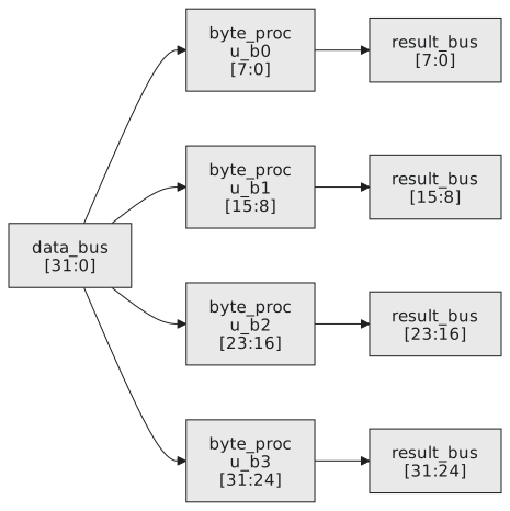
    byte_proc u_b0 (.byte_in(data_bus[7:0]),   .byte_out(result_bus[7:0]));
    byte_proc u_b1 (.byte_in(data_bus[15:8]),  .byte_out(result_bus[15:8]));
    byte_proc u_b2 (.byte_in(data_bus[23:16]), .byte_out(result_bus[23:16]));
    byte_proc u_b3 (.byte_in(data_bus[31:24]), .byte_out(result_bus[31:24]));
endmodule
The four slices cover every bit of both buses and do not overlap, so each bit of result_bus has exactly one driver (Figure 1).
Constants on ports
uart_tx u_uart (
    .clk      (clk),
    .rst_n    (rst_n),
    .baud_div (16'd868),
    .parity_en(1'b0),
    .stop_bits(2'b01),
    .data     (tx_data),
    .start    (tx_start),
    .tx       (tx_pin)
);
Size every literal to its port. To tie a 4-bit input to all ones write 4'hF, not 1'b1, which would be zero-extended to 4'h1.
Tying off
Outputs you do not use: a named wire, which you can then see in the waveform viewer, or empty parentheses. Inputs you do not use: a sized constant, always. An unconnected input is z, z becomes x in the first gate it meets, and an x in the carry-in of an adder makes every sum bit x.
adder u_adder (
    .a       (op_a),
    .b       (op_b),
    .cin     (1'b0),      // an input: tied
    .sum     (result),
    .overflow()           // an output: fine to leave
);
One driver
A wire has one driver. Connect two outputs to it and in simulation you get x wherever they disagree; in silicon you get two gates fighting, current through both, and possibly damage.
// wrong: two drivers
wire bad_net;
driver_a u_a (.y(bad_net));
driver_b u_b (.y(bad_net));

// right: separate wires, combined on purpose
wire out_a, out_b;
driver_a u_a (.y(out_a));
driver_b u_b (.y(out_b));
assign combined = out_a | out_b;
The one place multiple drivers are intended is an open-drain bus such as I²C, and Verilog has wor and wand net types for that, so that the intent is declared.
Name the wires
It is tempting to put expressions straight onto ports. A named wire for each connection documents what the signal is, shows up by name in waveforms, and appears by name in timing reports:
wire [3:0] alu_operand_b;      // b, inverted for subtraction
wire       ripple_carry_in;    // the +1 for two's complement

assign alu_operand_b   = sub_mode ? ~data_b : data_b;
assign ripple_carry_in = sub_mode;

rca_4bit u_adder (
    .a  (data_a),
    .b  (alu_operand_b),
    .cin(ripple_carry_in),
    .sum(result),
    .cout(carry_out)
);
Practice Exercise
nibble_alu has a SIGNED parameter, 4-bit inputs a and b, a 2-bit op, and outputs result, carry and overflow. Instantiate one for the low nibble of byte_a and byte_b with SIGNED 0 and one for the high nibble with SIGNED 1, driving the halves of an 8-bit byte_result, sharing a 2-bit alu_op, and leaving both overflows unconnected.
Solution
wire [7:0] byte_result;
wire [1:0] alu_op;
wire       carry_low, carry_high;

nibble_alu #(.SIGNED(0)) u_low (
    .a       (byte_a[3:0]),
    .b       (byte_b[3:0]),
    .op      (alu_op),
    .result  (byte_result[3:0]),
    .carry   (carry_low),
    .overflow()
);

nibble_alu #(.SIGNED(1)) u_high (
    .a       (byte_a[7:4]),
    .b       (byte_b[7:4]),
    .op      (alu_op),
    .result  (byte_result[7:4]),
    .carry   (carry_high),
    .overflow()
);
Each instance drives its own half of byte_result, so every bit has one driver.
The next article is about hierarchy as a design tool: building the adder from instances, and using generate to build an N-bit one without writing N instantiations.