Continuous Assignments
Section 4.4 described circuits by naming gates. This section describes them by writing equations. A gate on a schematic is always there, computing its output from its inputs from the moment power arrives. assign y = a & b; is that gate written down: not an instruction, but a statement that an AND gate exists with its output on y. That is dataflow modelling, and it is how nearly all combinational RTL is written.
The statement
assign wire_name = expression;
The right-hand side can use any operator from section 4.3, and whatever hardware the expression implies is what gets built:
assign sum        = a + b;                                   // an adder
assign {cout, s}  = {1'b0, a} + {1'b0, b};                   // the same adder, carry kept
assign y          = sel ? a : b;                             // a mux
assign eq         = (a == b);                                // an XOR tree
Read each one and ask what circuit it is. The answer is always the same kind of thing: some gates with inputs and an output wire.
The rules
It is continuous. Whenever anything on the right changes, the left changes, after a gate delay in silicon and instantly in an ideal simulation. Nothing polls and nothing is called.
It is concurrent. Every assign in a module is active at the same time, and the order they appear in is irrelevant. These are the same hardware:
assign sum = a + b;
assign eq  = (a == b);

assign eq  = (a == b);
assign sum = a + b;
The left side is a net. A reg cannot be driven by assign; that is the rule from section 4.2, and the compiler enforces it.
One driver per wire. Two assigns to the same wire are a conflict, an error in most tools and x in the rest. If a wire needs to take one of several values, that is a mux, and you write the mux:
assign y = sel ? a : b;
An assign can carry a delay, assign #5 y = a & b;, and the simulator honours it and the synthesiser ignores it, as section 4.1 said. It belongs in models, not in designs.
Two spellings
wire y;
assign y = a & b;    // explicit

wire y = a & b;      // declaration and assignment together
Both synthesise. The explicit form is the one to use in anything other than a throwaway, because the assign keyword is what a reader looks for.
What a set of assigns is
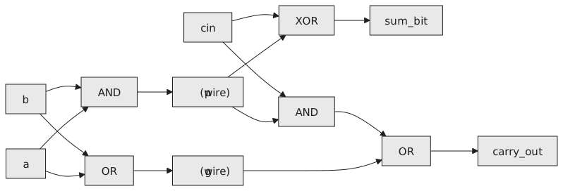
Four assigns describe a full adder bit:
assign p         = a ^ b;
assign g         = a & b;
assign sum_bit   = p ^ cin;
assign carry_out = g | (p & cin);
Every statement is a node in the schematic and its output wire; every name on the right is a wire from another node (Figure 1). The synthesiser maps each expression to cells of the library, and the names p, g, sum_bit and carry_out are the wires between them.
assign or always @(*)
Both describe combinational logic and the netlist is the same. The choice is readability.
| Logic | Use |
|---|---|
| one expression, one output | assign |
| a 2-to-1 or 4-to-1 mux | assign with ?: |
| an adder, a comparator | assign |
| several outputs from the same conditions | always @(*) |
| a decode with many cases | always @(*) with case |
| anything with a clock | always @(posedge clk), the only option |
If it fits in one expression, assign. If you find yourself four levels deep in ?: or writing the same condition for three outputs, an always block. A module mixes the two freely.
A half adder and a full adder
`timescale 1ns / 1ps
`default_nettype none

module half_adder (
    input  wire a,
    input  wire b,
    output wire sum,
    output wire carry
);
    assign sum   = a ^ b;
    assign carry = a & b;
endmodule

module full_adder (
    input  wire a,
    input  wire b,
    input  wire cin,
    output wire sum,
    output wire cout
);
    wire xor_ab;
    wire carry_1, carry_2;

    assign xor_ab  = a ^ b;
    assign sum     = xor_ab ^ cin;
    assign carry_1 = a & b;
    assign carry_2 = xor_ab & cin;
    assign cout    = carry_1 | carry_2;

endmodule
This is the five-gate full adder of the previous section, without naming a gate.
Practice Exercise
Write a 4-input priority encoder with assign only: input req[3:0], output grant[1:0] giving the index of the highest active request, and valid high when any request is active.
Solution
`timescale 1ns / 1ps
`default_nettype none

module priority_encoder_4to2 (
    input  wire [3:0] req,      // req[3] has the highest priority
    output wire [1:0] grant,
    output wire       valid
);
    assign valid = |req;

    assign grant = req[3] ? 2'd3 :
                   req[2] ? 2'd2 :
                   req[1] ? 2'd1 :
                            2'd0;
endmodule
The chain tests from the top down, so the highest active request wins. With no request, grant reads 0, the same as for req[0] alone, which is why valid exists: the reader of grant has to check it first.
The next article is a gallery: the common circuits of RTL, each as an assign, ending with a complete ALU in dataflow style.