Relational and Logical Operators
Every decision a circuit makes comes down to one bit: take the branch or not, FIFO full or not, count reached or not. Two families of operators produce that bit. Relational operators compare values; logical operators combine truth values. They look like their C equivalents, and one pair of them, && against &, is different enough from what a programmer expects to be worth its own section.
Relational operators
wire [7:0] a = 8'd100, b = 8'd50;

wire gt  = (a > b);    // 1
wire lt  = (a < b);    // 0
wire gte = (a >= b);   // 1
wire lte = (a <= b);   // 0
wire eq  = (a == b);   // 0
wire neq = (a != b);   // 1
The result is always one bit. The parentheses are not required but they are a good habit, for reasons the precedence article makes clear.
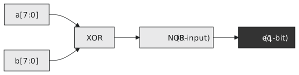
Equality is the cheap comparison: an XOR per bit and a tree to combine them, so the delay grows with $\log N$. Magnitude is a subtractor, a carry chain from bit 0 up, and the delay grows with $N$ (Figure 1). FPGAs have fast carry chains, so a wide compare is not disastrous, but it is longer than an equality test and it shows up on the critical path of wide counters and address decoders. When either would do, for instance detecting a counter at its last value that it never exceeds, use ==.
Case equality
Signals have four values, and an == with an x or z bit on either side gives x, which is right for hardware: an unknown voltage might be either. Sometimes in a testbench you want to ask whether a signal is exactly x. That is what === and !== are for:
wire [1:0] x = 2'bx0;

wire eq1 = (x == 2'b00);    // x: bit 1 is unknown
wire eq2 = (x == 2'bx0);    // x: == never matches an x
wire eq3 = (x === 2'bx0);   // 1: exact four-value match
wire eq4 = (x === 2'b00);   // 0
They are not synthesisable. Silicon has no x. Use them in testbenches to check that reset cleared every bit or that nothing unknown reached an output, and remember that if (out == 8'hxx) is never true because the comparison itself is x, which if treats as false; you need === there.
Logical operators
&&, || and ! work on the truth of whole expressions. Anything non-zero is true, zero is false, and the result is one bit:
wire valid = (count > 0) && (count < MAX) && enable;
wire fault = error_a || error_b || watchdog_expired;
For single-bit signals they behave the same as &, | and ~. For anything wider they do not.
Bitwise against logical
wire [3:0] a = 4'b1010;
wire [3:0] b = 4'b1100;

wire [3:0] bitwise_and = a & b;    // 4'b1000: bit by bit
wire       logical_and = a && b;   // 1'b1: both non-zero

wire [3:0] bitwise_or  = a | b;    // 4'b1110
wire       logical_or  = a || b;   // 1'b1
a & b is four AND gates in parallel and the result is four bits. a && b is two OR-reductions feeding one AND gate and the result is one bit. Use && and || to combine conditions and & and | to operate on data:
wire [7:0] masked  = data & 8'h0F;
wire [7:0] flagged = status | 8'h80;
wire [7:0] merged  = ({8{sel_a}} & a) | ({8{sel_b}} & b);   // an AND-OR mux
Mixing them up compiles cleanly and builds the wrong circuit.
In C, && stops evaluating when the left side is false. Simulators generally do the same, so (a != 0) && (b / a > 2) will not divide by zero in simulation. In hardware both sides exist and are always evaluated; there is no such thing as skipping a gate. Never rely on short-circuiting for correctness in RTL.
A range checker
`timescale 1ns / 1ps
`default_nettype none

module range_checker #(
    parameter WIDTH = 8,
    parameter LO    = 8'd10,
    parameter HI    = 8'd100
)(
    input  wire [WIDTH-1:0] value,
    output wire             in_range,   // LO <= value <= HI
    output wire             below,
    output wire             above
);
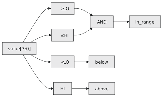
    assign in_range = (value >= LO) && (value <= HI);
    assign below    = (value < LO);
    assign above    = (value > HI);
endmodule
Two magnitude comparators and an AND gate (Figure 2). Exactly one of the three outputs is high at any time.
Comparator bugs live at the boundaries, so a testbench for this should try one below the low limit, the limit itself, something in the middle, the high limit and one above it:
module tb_range;
    reg [7:0] value;
    wire in_range, below, above;

    range_checker #(.LO(10), .HI(100)) dut (
        .value(value), .in_range(in_range), .below(below), .above(above)
    );

    initial begin
        value = 8'd9;   #10;   // below
        value = 8'd10;  #10;   // in range
        value = 8'd55;  #10;   // in range
        value = 8'd100; #10;   // in range
        value = 8'd101; #10;   // above
        value = 8'hxx;  #10;   // every output x
        $finish;
    end
endmodule
Practice Exercise
Write an 8-input priority encoder with a 3-bit output giving the index of the highest set bit, and a valid output, using only continuous assignments.
Solution
`timescale 1ns / 1ps
`default_nettype none

module priority_enc_8 (
    input  wire [7:0] in,
    output wire [2:0] out,
    output wire       valid
);
    assign valid = |in;

    assign out = in[7] ? 3'd7 :
                 in[6] ? 3'd6 :
                 in[5] ? 3'd5 :
                 in[4] ? 3'd4 :
                 in[3] ? 3'd3 :
                 in[2] ? 3'd2 :
                 in[1] ? 3'd1 :
                         3'd0;
endmodule
Each in[N] is a single bit used directly as a condition, the chain of conditionals gives the priority, and the OR reduction gives valid without a comparison.
Next: the bitwise operators in their own right, and the reduction operators that turn a whole vector into one bit, including a parity generator in a single line.