Viewing a First Floorplan
Everything in this module, up to this point, has lived in one of three places: hand arithmetic, a config file, or a log message describing what a tool would do. None of it has been a picture. That changes now.
Running the floorplan stage
With config.json assembled from the first article of this section, the floorplan stage is one interactive command after prep:
% prep -design counter8
[INFO]: Preparing OpenLane environment for counter8...
[INFO]: PDK: sky130A, standard cell library: sky130_fd_sc_hd

% run_floorplan
[INFO]: Generating floorplan...
[INFO]: Core area set to 5.00 5.00 45.00 45.00 (die 0.00 0.00 50.00 50.00)
[INFO]: Inserting endcap cells at row boundaries...
[INFO]: Inserting tap cells (sky130_fd_sc_hd__tapvpwrvgnd_1) per density rule...
[INFO]: Generating power distribution network...
[INFO]:   Core ring: met4/met5, width 1.60
[INFO]:   Vertical straps (met4): 3, Horizontal straps (met5): 3
[INFO]: Placing I/O pins using FP_PIN_ORDER_CFG: pin_order.cfg
[INFO]:   West: clk, rst_n, en | East: count[7:0]
[INFO]: Floorplanning complete.
[INFO]: Writing floorplan DEF to runs/counter8_run/results/floorplan/counter8.floorplan.def
Every line traces to an article in this module: the die and core to Section 3.1, the PDN to 3.2, the pins to 3.3, the taps to the previous article. A real tool run producing a real DEF, entirely from decisions you made by hand first.
Opening the DEF
A DEF (Design Exchange Format) file is plain-text, structured physical geometry: component placements, pin locations, special (power) net routing, and row and site definitions, readable by several independent tools. Two are worth opening it in, per Module 1.
In Magic, with the SKY130 technology file:
magic -T sky130A.tech runs/counter8_run/results/floorplan/counter8.floorplan.def
In KLayout, as an independent second viewer, the two-tool discipline from Module 1:
klayout runs/counter8_run/results/floorplan/counter8.floorplan.def
What you are looking at
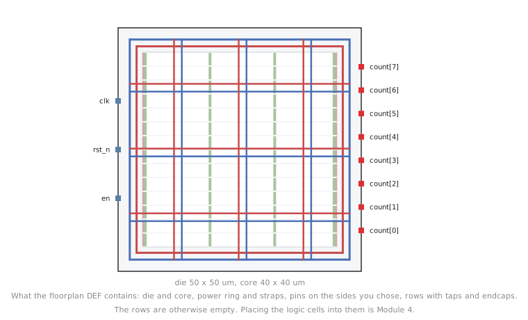
| What you see | What it is | Where it came from |
|---|---|---|
| Outer rectangle | Die boundary | 3.1.3, 50 by 50 µm |
| Inner rectangle, inset by the margin | Core boundary | 3.1.1 and 3.1.3, 40 by 40 µm, 5 µm margin |
| Thick traces around the core perimeter | Power ring (met4/met5) | 3.2.1, 3.2.3 |
| Thick traces crossing the interior | Power straps | 3.2.1, 3.2.3 |
| Marks on the west edge | clk, rst_n, en |
3.3.1, 3.3.3 |
| Marks on the east edge | count[7:0], in bit order |
3.3.1, 3.3.3 |
| Small repeating cells along the rows | Tap and endcap cells | 3.5.2 |
| Empty rows with no logic cells | Standard cell sites, unpopulated | Waiting for Module 4 |
That last row matters. This is a floorplan, not a placement. The rows exist, the sites exist, power and I/O are in, but counter8’s flip-flops and gates have not been dropped into position yet. That is Module 4.
This is the artefact a physical design engineer opens first, every time, before trusting an automated flow to keep going. A quick visual review catches gross errors (a die the wrong shape, pins on the wrong side, a missing ring) in seconds, long before they surface as a confusing failure three stages later. In whichever viewer you have, zoom into one corner of the core and find, distinctly, the ring, a strap terminating into it, and a tap cell in the nearest row. Finding all three in one small region is the fastest confirmation that the floorplan contains everything you specified, rather than taking the log’s word for it.
Practice Exercise
You open the DEF and the core is noticeably non-square, closer to 3:1 than the 1:1 you configured. Which two config fields from this section would you check first, and why those two?
Solution
Check FP_ASPECT_RATIO first. It directly controls the width-to-height ratio (3.1.2), and a value like 3.0 left in the config by mistake produces exactly this symptom. If it reads 1.0 and the shape is still wrong, check FP_CORE_UTIL next: an unexpectedly extreme utilisation combined with tool defaults or overrides can occasionally interact with the aspect ratio computation. These two are the first stop because they are the only inputs from this module that determine core shape. Pin order, PDN geometry and tap cells affect what is placed within the core, not its boundary.
The floorplan exists and you have seen it. In the next module we take the empty standard cell rows you just looked at and fill them: global placement, legalisation, and the first look at where every gate in counter8 actually ends up.