Orientation and Channel Spacing
The previous article gave a macro room. This one points it the right way.
A hard macro is not only a rectangle; it is a rectangle with pins fixed to specific sides, baked in at hardening time and immovable afterwards. You cannot ask a register file to grow a port on its west edge because that is where you would like one. What you can do is rotate or mirror the whole macro as a rigid unit, which is what orientation control gives you.
Orientation: rotating and mirroring the whole block
LEF and DEF orientation codes describe eight placements of a rectangular macro: the identity N (north, unrotated), three rotations (S, E, W), and four mirrored variants (FN, FS, FE, FW, where F is flipped). Whichever you pick, the macro’s internal layout and pin locations move rigidly with it. You are repositioning where its fixed pin edges point, not editing the macro. The only reason to change orientation is to make a macro’s pin edge face what it connects to rather than away from it.
An example
Suppose regfile_8x8 from the previous article has its data-output pins on its east edge (that is how it was hardened), and it feeds a second illustrative macro, alu_macro, whose input pins are on its west edge. You are placing alu_macro to the right of the register file.
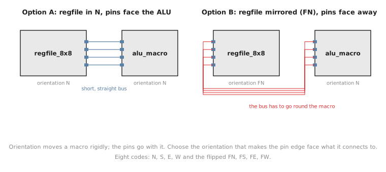
Option A is clearly right. With the register file in its default N, its east pins land directly across the gap from the ALU’s west pins, also in N, and the bus travels the shortest straight distance. Option B, mirroring the register file for no reason, points its pins the wrong way and forces the same bus round the macro’s body, adding wire length and using routing resources on other layers just to get past it.
The default N is only correct when it happens to align pins the way you need. There is no virtue in leaving every macro at its default; orientation is a tool used deliberately based on where each macro’s pins are and what they need to face.
Channel spacing: room to route between them
Orientation solves direction; it does not solve distance. Even with pins facing each other, the gap between two macros, the routing channel, must be wide enough to fit every wire crossing it plus whatever standard cells and buffers also live there. A channel that is too narrow cannot be widened after placement without moving a macro, and moving a hard macro after placement is far more disruptive than adjusting a channel during floorplanning. An illustrative rule of thumb: the channel must comfortably fit the widest bus crossing it (an 8-bit bus needs at least 8 side-by-side tracks) plus each macro’s halo on both sides of the gap. Commercial floorplanners flag channel-width violations once macros are placed and refuse to proceed to detailed routing until the gap is widened or a macro moved, another instance of the iteration loop this course keeps returning to.
Practice Exercise
A macro has its pins on its north edge. It connects to logic directly above it, with pins on that logic’s south-facing side. What orientation does the macro need?
Solution
None. The default N already works: the pins are on the north edge, and the thing it connects to is directly north, so the pins already face the right way. Orientation only changes when a macro’s pin edge points away from what it connects to.
With orientation and channel spacing reasoned through, in the next article we put a real macro placement file together: coordinates, orientation and halo, all specified for OpenLane.