Pad-Limited Versus Core-Limited Designs
Section 3.1 computed a 50 by 50 µm die for counter8, driven entirely by core area, utilisation and margin. That assumed the core was what set the die’s size. Time to check the assumption, because for a design this small it is probably wrong.
Two different bottlenecks
Every die has to satisfy two independent constraints at once: big enough to hold the core (cells plus routing), and enough perimeter to fit every I/O pad the design needs, at whatever pitch (centre-to-centre spacing) the pad cells require. Whichever demands the bigger die wins; the other rides along with room to spare.
- Core-limited: the die is exactly what Section 3.1’s arithmetic said, enough for the core plus margin, and the pads fit comfortably in that perimeter. The common case for large, logic-dense chips with modest pin counts.
- Pad-limited: the core would fit in a much smaller die, but there is not enough perimeter at that size to fit every pad at its minimum pitch, so the die grows purely to make room for I/O.
Pad-limited designs are far more common than newcomers expect, for the reason counter8 is about to show: small designs have small cores, but pad count does not shrink nearly as fast, because every design needs a baseline of power, ground and signal pads regardless of how little logic it has.
Checking counter8 against both
Section 3.1 gave the core-limited answer: a 50 by 50 µm die, perimeter $4 \times 50 = 200$ µm.
Now the pad-limited side. counter8 needs 11 signal pads and, like any real design, a few dedicated power and ground pads independent of signal count. Say 4 (two VDD, two VGND, for redundancy), for 15 pads total. Assume an illustrative pad pitch of 40 µm, a representative order of magnitude for small pad-limited test chips rather than a PDK-quoted number. The minimum perimeter for 15 pads at that pitch:
$$P_{\min} = \text{pad count} \times \text{pad pitch} = 15 \times 40 = 600 \text{ µm}$$
| Constraint | Required perimeter |
|---|---|
| Core-limited (from 3.1) | 200 µm |
| Pad-limited (this article) | 600 µm |
600 µm is three times 200. counter8’s die size is not set by its core; it is set by its pads, by a wide margin. A square die with a 600 µm perimeter has a 150 µm side, nine times the area of the 50 by 50 core-limited estimate, purely to fit the pad ring.
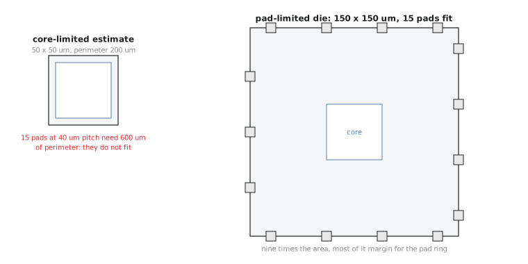
This is why tiny educational and shuttle designs so often look wasteful in photos, with huge margins of empty silicon around a small block of logic. That is not waste; it is the pad ring doing its job. counter8 is a realistic pad-limited example, not a contrived one. Computing only the core-limited size and treating it as final, without checking pad count against pitch, produces a die spec that cannot be built. OpenLane’s I/O placement step fails outright when it cannot fit the required pads into the space you gave it.
Practice Exercise
A design has a core-limited die perimeter of 320 µm. It needs 25 pads (signal plus power and ground) at a 35 µm pitch. Is it pad-limited or core-limited, and what perimeter should be used?
Solution
Pad-limited perimeter = 25 × 35 = 875 µm, far larger than the 320 µm core-limited figure, so the design is pad-limited. The die must have at least 875 µm of perimeter (about 219 µm per side if square). Using the smaller core-limited figure would give a die that cannot fit all 25 pads.
Knowing which side a pin goes on and how big the die really needs to be sets up the last piece of I/O placement: in the next article we write an actual pin order file and hand it to OpenLane.