Halos and Blockages
Section 3.3 placed the pins. Section 3.4 is about the one kind of block that does not fit into standard cell rows.
counter8 is small enough that everything in it is a standard cell: flip-flops and gates from sky130_fd_sc_hd, all the same height, all droppable into rows by the tool. Most real designs are not that uniform. Sooner or later you place a hard macro, a register file, an SRAM, a pre-hardened analog block, and macros play by different rules. The first rule is the halo.
What a halo is
A macro halo is a keep-out margin around a hard macro’s footprint that neither standard cells nor most routing may enter. It is not decorative spacing. Hard macros are pre-designed, fixed-layout blocks with their own internal power grid, their own metal usage right up to their edge, and often their own DRC requirements at the boundary. Standard cells placed too close can violate the macro’s boundary rules or make routing between the macro’s pins and the outside needlessly congested. It is the clearance you leave around a piece of furniture bolted to the floor: enough room to walk round it, plug things into it and service it.
Standard cells never need a halo around each other because they are designed to abut. That is the point of a library sharing a common height and rail pitch. Macros break that assumption by design, so the floorplanner has to carve out and protect their footprint explicitly.
Computing the keep-out rectangle
Take an illustrative macro, regfile_8x8, an 8-word by 8-bit register file standing in for the kind of block Module 10’s macro integration project uses, with a footprint of 60 µm wide by 40 µm tall and a halo of 5 µm on every side. The keep-out rectangle, the total area nothing else may enter, adds the halo to both sides of each dimension, as the core-to-die margin did in Section 3.1:
$$w_{\text{keepout}} = w_{\text{macro}} + 2 \times \text{halo} = 60 + (2 \times 5) = 70 \text{ µm}$$ $$h_{\text{keepout}} = h_{\text{macro}} + 2 \times \text{halo} = 40 + (2 \times 5) = 50 \text{ µm}$$
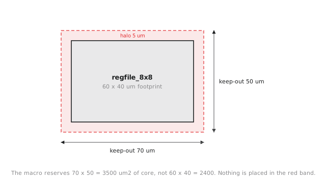
The macro is 60 × 40 = 2400 µm², but the space it reserves in the floorplan is 70 × 50 = 3500 µm². That is the number the floorplanner works with, not the raw footprint. Budgeting core area (the utilisation arithmetic from Section 3.1) with only the raw footprint, forgetting the halo, is a common mistake; on a design with several macros the halos add up to a real fraction of the core, and leaving them out means coming up short once placement runs.
A blockage is the general term: any region of the core where standard cell placement (and often routing on specific layers) is disallowed, for any reason. A halo is one macro-driven kind of blockage. Blockages are also used to reserve space for a planned future macro or to keep a region clear for a routing resource.
Try one yourself: a 100 by 30 µm macro with an 8 µm halo. The keep-out should come out at 116 by 46 µm.
Practice Exercise
Two macros need placing: A is 50 by 50 µm with a 6 µm halo, B is 80 by 20 µm with a 4 µm halo. Compute each keep-out rectangle and area, and say which consumes more effective core area.
Solution
A: (50 + 12) × (50 + 12) = 62 × 62 = 3844 µm². B: (80 + 8) × (20 + 8) = 88 × 28 = 2464 µm². A’s raw footprint (2500 µm²) is already larger than B’s (1600 µm²), and A’s bigger halo widens the gap, so A costs nearly 1.6 times as much keep-out area. Halo width compounds with footprint, so it is the keep-out rectangle you budget against, never the raw footprint.
A halo protects a macro’s boundary. In the next article we look at what happens when two macros sit near each other: orientation, and the routing channel that has to fit between them.