Computing a Floorplan by Hand
The last two articles produced three separate pieces: how much core area, what shape, and how much margin around it. None of them is a floorplan on its own. A floorplan is all three combined into one spec you could read off to a tool, and, the point of this article, one the tool works out for you every time it runs whether or not you ever did it yourself. Let us assemble it once, completely, for counter8.
The inputs
Carrying forward what the previous two articles computed:
- Total cell area (from the Module 2 report): 720 µm²
- Target core utilisation: 45 percent
- Aspect ratio: 1:1, the right default for this small design
- Core-to-die margin: 5 µm on every side, enough for an I/O ring and its wiring on a design this small
The fourth number has not appeared yet. Margin does not come from a formula the way core area does; it is chosen from how much I/O cell height and routing space the pad ring around your design needs. 5 µm is a reasonable illustrative allowance for something as small as counter8, which has a modest pin count as Section 3.3 shows.
Assembling the spec
Step 1, core area (from the first article):
$$\text{Core Area} = \frac{720}{0.45} = 1600 \text{ µm}^2$$
Step 2, core dimensions at 1:1 (from the second):
$$w_{\text{core}} = h_{\text{core}} = \sqrt{1600} = 40 \text{ µm}$$
Step 3, die dimensions, adding the margin to every side:
$$w_{\text{die}} = w_{\text{core}} + 2 \times \text{margin} = 40 + (2 \times 5) = 50 \text{ µm}$$ $$h_{\text{die}} = h_{\text{core}} + 2 \times \text{margin} = 40 + (2 \times 5) = 50 \text{ µm}$$
That is the whole floorplan:
| Field | Value |
|---|---|
| Total cell area | 720 µm² |
| Target utilisation | 45% |
| Core width | 40.00 µm |
| Core height | 40.00 µm |
| Core-to-die margin | 5.00 µm (all sides) |
| Die width | 50.00 µm |
| Die height | 50.00 µm |
Reading it back as coordinates
Tools do not describe floorplans as widths and heights floating in space. They describe coordinate boxes anchored at an origin, usually (0, 0) at the die’s lower-left corner:
DIE_AREA:   0.00  0.00  50.00  50.00     (llx lly urx ury, in microns)
CORE_AREA:  5.00  5.00  45.00  45.00     (the die box inset by the 5 um margin)
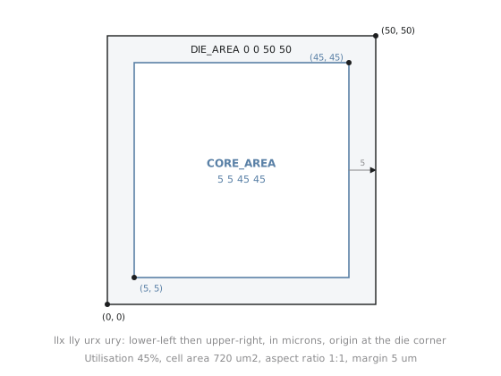
This is almost exactly the shape of the DIE_AREA field you would write into config.json, and the same convention you will see in the DEF file opened in Magic or KLayout at the end of this module. Get comfortable with lower-left, upper-right box notation now; it recurs for the rest of the course.
Every number in the table traces back to one input you chose (utilisation, aspect ratio, margin) and one synthesis gave you (cell area). Nothing is arbitrary, so when a floorplan comes out wrong you know exactly which of the four inputs to question. One mistake to avoid: margin is added on both sides of each dimension. A 5 µm margin adds 10 µm to each axis, not 5. That off-by-two shows up as a die that is mysteriously too small once real I/O cells have to fit.
Sanity-check the spec: does the core area (40 × 40 = 1600 µm²) holding 720 µm² of cells give back the 45 percent target? 720 / 1600 = 0.45. This round-trip check is a fast, free way to catch arithmetic slips before feeding numbers to a tool.
Practice Exercise
A design has a cell area of 4,000 µm², a target utilisation of 50 percent, an aspect ratio of 1:1, and a margin of 8 µm on every side. Compute the full spec: core area, core width and height, die width and height.
Solution
Core area = 4000 / 0.50 = 8000 µm². At 1:1, core width = height = √8000 ≈ 89.44 µm. Die width = height = 89.44 + (2 × 8) = 105.44 µm. As boxes with the origin at the die’s lower-left: DIE_AREA: 0 0 105.44 105.44, CORE_AREA: 8 8 97.44 97.44. The core box is the die inset by 8 µm on each side, and its own width (97.44 − 8 = 89.44) matches the core dimension computed above.
With a complete floorplan for counter8, the next section turns to something die area alone does not address: how power reaches every cell inside it. That is power planning, starting with rings and straps.