Tap Cells and Endcaps
Every cell this module has reasoned about so far has been logic: flip-flops and gates implementing counter8. There is a second category that does no logic, connects to no net in your Verilog, and still has to go into every design built on SKY130: the tap cell.
Why tap cells exist
A CMOS standard cell sits on a shared substrate, and that substrate has to be tied to a defined voltage: the well needs a tap to VDD (or VSS, depending on the well) at regular intervals across the die. Skip this, or space the taps too far apart, and you risk latch-up: a parasitic bipolar structure inherent to CMOS can turn on under certain conditions and create a low-resistance short between the supply rails that a reset cannot clear, sometimes destructively. Tap cells keep the substrate pinned close enough to its intended voltage, everywhere, that the parasitic path never activates.
Because this is a substrate concern rather than a logic one, tap cells appear nowhere in the Verilog, the netlist or the SDC. They are inserted as a physical requirement, during floorplanning, by the tool.
Endcap cells solve a related problem: they cap the ends of every standard cell row, providing proper well and boundary termination so the first and last logic cell in a row does not sit against an unterminated, rule-violating edge. Taps are periodic maintenance along a row; endcaps are the bookends.
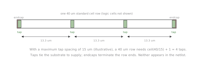
Neither does anything you would simulate. A netlist with every tap stripped out would behave identically in simulation. The failure they prevent is physical and substrate-level, invisible at the logic level, which is the kind of requirement physical design adds on top of a functionally complete design.
Computing how many a row needs
SKY130’s actual maximum tap spacing is a specific number in the PDK’s rule deck, not something to memorise here. For the arithmetic, assume an illustrative rule of at least one tap every 15 µm along a row.
counter8’s core is 40 µm wide, so every row spans 40 µm. How many taps does a row need under the 15 µm rule?
$$N_{\text{taps}} = \left\lceil \frac{\text{row length}}{\text{max spacing}} \right\rceil + 1 = \left\lceil \frac{40}{15} \right\rceil + 1 = 3 + 1 = 4$$
Four taps per row minimum, one near each end and enough in between that no gap exceeds 15 µm. Check: four taps across 40 µm, evenly spread, give three gaps of about 13.3 µm, under the ceiling.
| Row length | Max spacing | Taps needed |
|---|---|---|
| 40 µm (this example) | 15 µm | 4 |
| 100 µm | 15 µm | 8 |
| 100 µm | 25 µm | 5 |
Tap count is not something you configure or optimise. The PDK’s rule and the row length set the minimum and OpenLane inserts what is required. The only thing you control is row length, indirectly, through the utilisation and aspect ratio decisions from Section 3.1.
What OpenLane does
Tap and endcap insertion happens automatically inside the floorplan stage, with no dedicated knob in a standard SKY130 flow:
% run_floorplan
[INFO]: Generating floorplan...
[INFO]: Inserting endcap cells at row boundaries...
[INFO]: Inserting tap cells (sky130_fd_sc_hd__tapvpwrvgnd_1) per density rule...
[INFO]:   Row 0 (y=5.00): 4 tap cells inserted
[INFO]:   Row 1 (y=7.72): 4 tap cells inserted
...
You will see these as real geometry, with everything else this module configured, in the next article.
Practice Exercise
A row is 90 µm long and the illustrative maximum tap spacing is 20 µm. How many taps does the row need, minimum?
Solution
N = ceil(90 / 20) + 1 = 5 + 1 = 6 taps. Six taps across 90 µm, evenly spread, give five gaps of 18 µm, under the 20 µm ceiling, confirming that the ceiling-plus-one form accounts for needing a tap at both ends of the row.
Every piece of this module, floorplan shape, power grid, pins, macro placement and now taps, has existed only on paper or in a config. In the next article, the last of the module, we run run_floorplan for real and open the result.