Aspect Ratio and Core-to-Die Margin
The previous article produced a core area of 1600 µm². That is not one shape; it is an infinite family of rectangles. A 40 by 40 µm square has that area. So does 160 by 10. So does 1600 by 1. All three satisfy the arithmetic. Only one is something you would want to route. That is what aspect ratio decides, the second number you choose.
Why shape matters, not only area
Aspect ratio is core width divided by core height. 1:1 is a square; 2:1 is twice as wide as tall.
Extreme ratios hurt for a physical reason: they force some signals to travel much farther than they otherwise would. In a long thin core, a net joining a cell near one end to a cell near the other has to cross the whole long dimension, and every wire that does so competes for the same limited routing tracks running that way, creating a corridor of congestion down the middle of the die however sparse the design’s connectivity is.
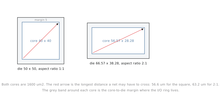
A near-square core minimises the worst-case distance between any two points, which is what you want when the design’s connectivity has no strong directional bias. Designs that are naturally pipeline-shaped, a chain of stages each talking only to its neighbours, can benefit from a matching elongated floorplan, but that is a deliberate choice made with knowledge of the design’s structure, not a default. Commercial dies are rarely perfect squares either; the package, how several blocks tile together, or a reticle constraint often dictates the shape. Absent an external reason, physical designers default to close to 1:1 because it is the safest bet for routability.
Core-to-die margin: room for the pad ring
Aspect ratio decides the core’s shape. The core-to-die margin decides how much die is wrapped around the core before the boundary. That margin is not wasted space. It is where the I/O ring lives: the pads or pins, the ESD protection cells, and the routing from the core edge to the pads. The grey band around each core in Figure 1 is that margin.
Skip it, or make it too thin, and there is physically no room for the I/O cells and their wiring, a problem OpenLane reports at floorplan time, which is exactly why this module comes before Module 4’s placement.
Computing both by hand
Take the 1600 µm² core from the previous article at two aspect ratios.
At 1:1 (width equals height):
$$w = h = \sqrt{1600} = 40 \text{ µm}$$
At 2:1 (width is twice the height):
$$2h^2 = 1600 \implies h^2 = 800 \implies h \approx 28.28 \text{ µm}, \quad w \approx 56.57 \text{ µm}$$
Same area, a visibly different shape:
| Aspect ratio | Width | Height | Area (check) |
|---|---|---|---|
| 1:1 | 40.00 µm | 40.00 µm | 1600.0 µm² |
| 2:1 | 56.57 µm | 28.28 µm | 1600.0 µm² |
For a small, control-dominated design like counter8 with no directional structure, 1:1 is the right default, and that is the shape this module carries into the next article’s complete floorplan. Do not pick an aspect ratio to match the shape of your RTL hierarchy or your source file layout. It is a physical routing decision driven by connectivity and packaging, and has nothing to do with how the Verilog is organised.
Practice Exercise
A design needs a core area of 2500 µm². Compute its width and height at a 4:1 aspect ratio, and say in one sentence why you would want a strong reason (a known pipeline structure, say) before choosing a ratio this extreme.
Solution
At 4:1, width = 4 × height, so 4h² = 2500, h² = 625, h = 25 µm, w = 100 µm. A 100 by 25 µm core. The worst-case distance across the long dimension is now 100 µm against about 50 µm for a same-area square (√2500 ≈ 50), so nets that cross the full core travel twice as far, concentrating routing demand into a long narrow corridor unless the design’s connectivity is known to be similarly elongated, such as a strict pipeline where stage N only talks to stage N+1.
With area and shape settled, in the next article we combine utilisation, aspect ratio and margin into one complete floorplan spec for counter8, the numbers you would hand to a tool.