Die Size and Utilisation
Module 2 ended with a netlist that passed the red-flag checklist. Module 3 gives it somewhere to live.
Every netlist so far has been a list of instances with no address. The synthesis report told you counter8 needs some number of standard cells, each with a known footprint, but never where they go or how much silicon they get. That is the first question physical design asks, and the question this module answers: how big is the piece of silicon, and what shape is it? The first number you pick is core utilisation.
What utilisation measures
Core utilisation is the fraction of the core area, the region inside the die reserved for standard cells, that is occupied by cell footprints once placement is done:
$$\text{Utilization} = \frac{\text{Total Standard Cell Area}}{\text{Core Area}}$$
Rearranged, this is the equation you will use constantly:
$$\text{Core Area} = \frac{\text{Total Cell Area}}{\text{Target Utilization}}$$
Note what 100 percent would mean: every square micron of the core covered edge to edge by cells, with nothing left over. That should sound alarming, and it is. It is not only unrealistic, it is impossible to route. Wires need somewhere to live too. Cells occupy the lower metal layers near the substrate, routing tracks above them need clearance, and the placer needs empty sites to legalise cells into rows, shuffle things during optimisation, and leave room for the buffers a clock tree or a timing fix inserts later. A fully utilised core has no room to route, no room to fix timing, and no room for the tool to do its job.
In practice, target utilisation for a sky130_fd_sc_hd design lands somewhere in the 40 to 65 percent range depending on how congested the connectivity is. Dense, highly connected logic (wide muxes, heavy fanout) wants a lower target for routing headroom; sparse, register-dominated logic can push higher.
Utilisation as a routability knob
It helps to stop thinking of utilisation as an area-efficiency number and start thinking of it as a routing-headroom knob. Figure 1 shows the same core at two settings.
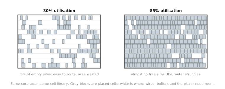
Push it too high and you will not see the problem here. You see it downstream, when the router (Module 6) reports congestion or unroutable nets and sends you back to this stage to loosen up. A reasonable value now saves an iteration later.
Computing it by hand
The reference design for this module is counter8, an 8-bit synchronous up-counter with an active-low reset and an enable. Suppose the Module 2 synthesis report for it, mapped to sky130_fd_sc_hd, showed this (illustrative numbers standing in for a report you would read yourself):
=== counter8 stat report (sky130_fd_sc_hd) ===
Number of cells:                 46
  DFF cells:                      8
  Combinational cells:           38
Chip area for module '\counter8': 720.4 (rounded here to 720 um2)
Target 45 percent, a reasonable, slightly conservative choice for a small control-heavy design. The required core area is:
$$\text{Core Area} = \frac{720 \text{ µm}^2}{0.45} = 1600 \text{ µm}^2$$
That one number, 1600 µm², is the core silicon counter8 needs. It says nothing about shape. A 1600 µm² core could be a 40 by 40 µm square or a 1600 by 1 µm sliver that would be a routing nightmare. Shape is the next article’s job.
Do not confuse core area with die area. Core area is where standard cells go. Die area is the whole chip: core plus the margin around it for I/O pins, the pad ring and clearance. Core first, then grow it into a die in the third article of this section.
Open config.json for any design you have prepped and find FP_CORE_UTIL (if absent, OpenLane defaults it to 50). That integer is exactly the denominator you just used. Change it from 45 to 70 and predict, before rerunning run_floorplan, whether the core shrinks or grows. It shrinks: the same cell area divided by a bigger number.
Practice Exercise
A design synthesizes to a total cell area of 1,140 µm². The team wants 38 percent utilisation to leave extra routing margin for a congested clock-gating network. What core area should you request?
Solution
Core area = 1140 / 0.38 = 3000 µm². The arithmetic is identical to the worked example; only the inputs changed. A lower target (38 percent against our 45) gives a proportionally larger core for the same cell area, which is the routing-headroom trade: the team is spending silicon to buy routing room, presumably because they know the clock-gating network will be dense.
Core area answers how much. In the next article we answer what shape, with aspect ratio and the margin around the core that makes room for I/O.