Module 2: Combinational Circuit Design
From analysing circuits to designing them
Module 1 gave you the language: Boolean algebra, gates, Karnaugh maps, and the standard blocks. Given a circuit, you can now say what it does. Module 2 asks for the harder thing. You are given a specification, “add two N-bit numbers”, and you have to produce the circuit, and then decide whether it is fast enough, small enough, and free of glitches.
The device you are reading this on is doing addition right now, billions of times a second, in thousands of places at once. Every memory address, every pixel coordinate, every audio sample goes through some version of the circuits in this module. And every one of those adders has the same problem: the carry has to travel from the least significant bit to the most significant, and that takes time. Most of what has been invented in adder design over sixty years exists to get round that one delay.
What the module covers
There are four sections and 21 articles.
| Section | Articles | Topics |
|---|---|---|
| 2.1 Adder circuits | 6 | Half and full adders, ripple carry, carry lookahead, carry select, choosing between them |
| 2.2 Subtractors and the ALU | 5 | Two’s complement subtraction, the adder/subtractor, ALU design, a 4-bit ALU, status flags |
| 2.3 Multipliers and shifters | 5 | Partial products, the array multiplier, Wallace trees, shift operations, the barrel shifter |
| 2.4 Hazards | 5 | What a hazard is, static and dynamic hazards, detecting and removing them, when they matter |
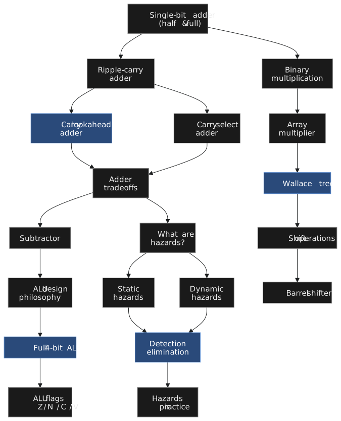
The sections build on one another. The adders feed directly into the ALU, and the hazards section needs real circuits to analyse, so take them in order.
What you will build
The centrepiece is a 4-bit ALU with arithmetic and logic operations and the four standard status flags: zero, negative, carry and overflow. Figure 2 shows it. Every block in that diagram is something you will have designed from Boolean equations by the end of section 2.2.

The adder/subtractor handles ADD and SUB by inverting one operand and setting the carry-in. The logic unit computes the bitwise operations in parallel. An 8-to-1 mux picks the result from the opcode. The flag logic watches the result and the carry chain. Structurally this is the same ALU as the one in the 6502 that ran the Apple II, only narrower, and once you have built this one you can read that schematic.
Many designers treat the ALU as something the synthesis tool produces from a plus sign. That is fine until timing fails, or a carry flag misbehaves, or signed overflow shows up somewhere unexpected. The designer who has built one knows where to look.
What you will be able to do
- Derive the half adder and full adder from truth tables and draw them at gate level.
- Build an N-bit ripple-carry adder and explain why its delay grows linearly with N.
- Derive generate and propagate signals and build a 4-bit carry-lookahead adder.
- Explain the carry-select adder and the area it trades for speed.
- Build an adder/subtractor with XOR gates and a mode input.
- Define the Z, N, C and V flags and implement each as a Boolean function.
- Design a 4-bit ALU with eight operations chosen by a 3-bit opcode.
- Explain binary multiplication as partial products and how an array multiplier realises them.
- Describe Wallace tree reduction and why it is faster than an array.
- Implement logical and arithmetic shifts, and a barrel shifter that shifts by any amount in one pass of muxes.
- Define static and dynamic hazards, find them on a Karnaugh map, and remove them with consensus terms.
- Judge when a hazard matters and when it can be ignored.
Time
One article a day gets you through in about three weeks. The exercises in sections 2.1 and 2.2 are not optional: carry lookahead and flag logic do not stick from reading alone, and you need to grind through the derivation by hand at least once.
Section 2.1 starts with the question of what it takes to add two numbers in silicon.