Dynamic Hazards
A static hazard is a brief wobble on an output that should have stayed still. A dynamic hazard is worse: the output is supposed to change, once, and instead it changes, changes back, and changes again. A signal that should go from 0 to 1 does 0, 1, 0, 1. To a counter or a latch that looks like three events.
Dynamic hazards are rarer than static ones, and they cannot happen at all in a two-level circuit. Where they turn up is in multi-level logic, which mostly means logic that a synthesis tool has restructured for area or speed, or that an FPGA has mapped across several lookup tables.
Definition
A dynamic hazard is three or more transitions on the output in response to a single input change, when exactly one was expected.
| Hazard | Output should | Output does |
|---|---|---|
| static-1 | stay at 1 | 1, 0, 1 |
| static-0 | stay at 0 | 0, 1, 0 |
| dynamic | change once | 0, 1, 0, 1 or 1, 0, 1, 0 |
Three is the minimum: the correct direction, a reversal, and the correct direction again.
Why three levels are needed
In a two-level circuit every path from an input to the output goes through at most an inverter, one AND gate and the OR gate. The paths can have different delays, but they all arrive at the single OR gate, and the OR gate’s output can only go one way. It may hesitate if its inputs arrive at different times with opposite effects, which is a static hazard, but once the slowest input has arrived it is settled. It cannot go back and forth.
With three levels, an input change can reach the output through the first and second levels, then reach the second level again by a slower route and reverse the first effect, then arrive by a third route and reverse it again. Three waves of cause and effect, three transitions.
So if a circuit shows a dynamic hazard it has at least three levels of logic, and if you keep a critical signal in two-level form you have ruled dynamic hazards out. Static hazards remain possible and are handled as in the last article.
What it looks like
Suppose there are three paths from input $A$ to the output with increasing delays and alternating effect: the fastest pushes $F$ high when $A$ rises, the next pushes it low, the slowest pushes it high again. Figure 1 shows what the output does.
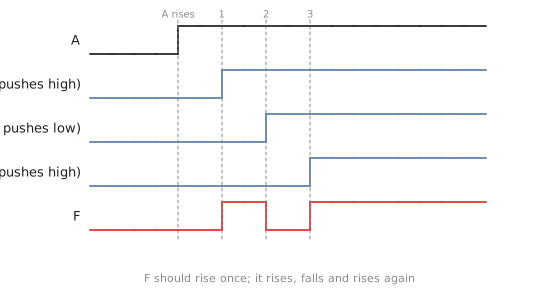
$F$ rises when the fast path arrives, falls when the middle path arrives, and rises for good when the slow path arrives. The final value is right. A flip-flop that samples between the first and second arrivals sees 1, one that samples between the second and third sees 0, and one that samples after the third sees 1.
A three-level circuit
Figure 2 shows $F = \overline{\overline{AB} \cdot \overline{AC}}$, three levels of NAND, which is $A(B + C)$.
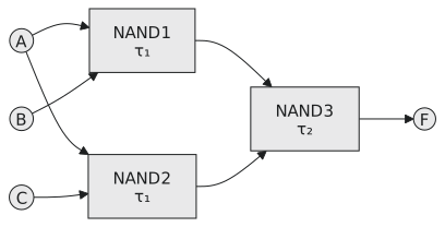
With $B = C = 1$ and $A$ rising, the two paths from $A$ are symmetrical and arrive together, so this particular circuit does not misbehave. But add a buffer chain on one branch, or embed it in a larger network where the branches pick up different amounts of logic, and the paths become unequal. Any three-level circuit with three paths of noticeably different delay and alternating polarity can show a dynamic hazard.
Where synthesis creates them
The realistic source of dynamic hazards is the synthesis tool. It splits a wide gate into a cascade of narrow ones, which adds levels. It shares an intermediate node between several functions to save area, which gives paths of unequal depth into the same gate. On an FPGA it maps a function across two or three LUTs in series, with the carry chain running alongside at a different speed. None of this is visible in your RTL.
The way to see it is gate-level simulation with timing annotation from an SDF file. The RTL simulator, with zero delays, shows nothing. The annotated simulation shows the glitch as a narrow pulse. For a synchronous path with timing met it is harmless; for an asynchronous control signal it is a serious finding.
Removing dynamic hazards
Three methods, in order of preference.
Keep the signal in two-level logic. A critical asynchronous signal implemented as two-level SOP or POS cannot have a dynamic hazard. You may need to stop the tool restructuring it, with a keep or dont_touch attribute on the module or cells, and on an FPGA by keeping the function inside a single LUT.
Flatten and add redundant terms. Flatten the multi-level function to its two-level form, apply the static-hazard procedure to that, and implement the result. This may cost more area than the original but is guaranteed hazard-free.
Register the signal. Put a flip-flop in the path. Glitches do not pass through a flip-flop whose timing is met. It costs a clock cycle of latency, and in a pipelined design that split may be there already for timing reasons.
For an FPGA design the practical rule is that no asynchronous output or control signal should leave combinational logic unregistered. If the design really needs one, analyse it for both kinds of hazard.
| static-1 | static-0 | dynamic | |
|---|---|---|---|
| intended | stay at 1 | stay at 0 | change once |
| observed | 1, 0, 1 | 0, 1, 0 | several reversals |
| minimum levels | 2 | 2 | 3 |
| found by | map, adjacent 1s | map, adjacent 0s | path delay analysis |
| removed by | redundant product | redundant sum | two-level form or a register |
| how common | common | moderate | rare, mostly after synthesis |
Practice Exercise
Problem 1. A three-level circuit has three paths from $A$ to $F$ with delays of 2, 4 and 6 gate delays, pushing $F$ high, low and high respectively when $A$ rises. Sketch $F$, count its transitions, and classify the hazard.
Solution
$F$ rises at 2, falls at 4 and rises at 6: three transitions where one was expected. The output is supposed to change, so this is not a static hazard; it is a dynamic hazard.
Problem 2. The synthesis report shows an asynchronous write enable implemented across four levels of logic. Can it have a dynamic hazard, and what would you do?
Solution
Yes. It needs three paths from the changing input with different delays and alternating polarity, and four levels of restructured logic on an asynchronous signal is exactly where that happens. Either flatten the enable to two-level form, remove its static hazards, and constrain the tool to keep it that way, or register the signal so it becomes synchronous, at the cost of one cycle of latency. In either case check it with an SDF-annotated gate-level simulation.
The next article turns the detection and removal of static hazards into a procedure you can follow step by step, including what to do about don’t-cares.