The Adder/Subtractor Unit with Flags
In the last article we made the adder subtract. In this one we make it report what happened. A circuit that adds and subtracts is useful; a circuit that also tells you whether the result was zero, negative, or overflowed is a processor building block. Those four one-bit answers, the flags, are how every conditional branch in every program is decided. This article wires them up, checks the unit against four cases that cover the corners, and shows how two 4-bit units make an 8-bit one.
The interface
| Signal | Width | Direction | Meaning |
|---|---|---|---|
| A | 4 | in | first operand |
| B | 4 | in | second operand |
| sub | 1 | in | 0 = add, 1 = subtract |
| S | 4 | out | result |
| Z | 1 | out | result is zero |
| N | 1 | out | result is negative |
| C | 1 | out | carry out, or no-borrow for subtraction |
| V | 1 | out | signed overflow |
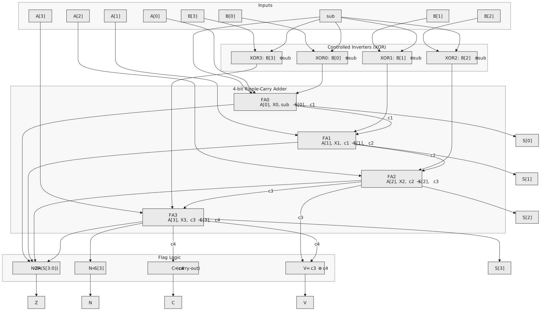
Watch the carry names in the figure. $c_1$ to $c_3$ are the internal ripple carries; $c_3$ is the carry into FA3, the most significant adder, and $c_4$ is the carry out of it. The overflow flag needs both.
The flags
Zero. $Z = \overline{S_3 + S_2 + S_1 + S_0}$, a 4-input NOR. Z is 1 only when every result bit is 0. In practice a 4-input NOR is built as two NOR2 gates feeding a third, two gate levels.
Negative. $N = S_3$. The most significant bit of the result is the sign bit in two’s complement. A wire, no gates.
Carry. $C = c_4$, the carry out of FA3. After an addition, C = 1 means the unsigned result exceeded 15. After a subtraction, C = 1 means no borrow, that is $A \geq B$ unsigned, and C = 0 means a borrow occurred.
Overflow. $V = c_3 \oplus c_4$. One XOR comparing the carry into the top bit with the carry out of it. If they differ, the sign bit is wrong.
Four test cases
Case 1: 3 + 4. $A = 0011$, $B = 0100$, sub = 0. The XOR layer passes B through, carry-in 0.
| Bit | A | X | Cin | Sum | Cout |
|---|---|---|---|---|---|
| 0 | 1 | 0 | 0 | 1 | 0 |
| 1 | 1 | 0 | 0 | 1 | 0 |
| 2 | 0 | 1 | 0 | 1 | 0 |
| 3 | 0 | 0 | 0 | 0 | 0 |
$S = 0111$ (+7). Z = 0, N = 0, C = 0, V = 0. Correct, no overflow.
Case 2: 6 + 4, signed overflow. $A = 0110$, $B = 0100$, sub = 0.
| Bit | A | X | Cin | Sum | Cout |
|---|---|---|---|---|---|
| 0 | 0 | 0 | 0 | 0 | 0 |
| 1 | 1 | 0 | 0 | 1 | 0 |
| 2 | 1 | 1 | 0 | 0 | 1 |
| 3 | 0 | 0 | 1 | 1 | 0 |
$S = 1010$. $c_3 = 1$, $c_4 = 0$. Z = 0, N = 1, C = 0, V = 1. The true sum is +10, outside the signed range, and the pattern $1010$ reads as −6. Only V tells you the result is wrong. As an unsigned sum, 6 + 4 = 10 = $1010$ is fine, and C = 0 confirms it.
Case 3: 6 − 3. $A = 0110$, $B = 0011$, sub = 1. The XOR layer gives $X = 1100$, carry-in 1.
| Bit | A | X | Cin | Sum | Cout |
|---|---|---|---|---|---|
| 0 | 0 | 0 | 1 | 1 | 0 |
| 1 | 1 | 0 | 0 | 1 | 0 |
| 2 | 1 | 1 | 0 | 0 | 1 |
| 3 | 0 | 1 | 1 | 0 | 1 |
$S = 0011$ (+3). $c_3 = 1$, $c_4 = 1$. Z = 0, N = 0, C = 1, V = 0. C = 1 means no borrow. Correct.
Case 4: 3 − 6. $A = 0011$, $B = 0110$, sub = 1. $X = 1001$, carry-in 1.
| Bit | A | X | Cin | Sum | Cout |
|---|---|---|---|---|---|
| 0 | 1 | 1 | 1 | 1 | 1 |
| 1 | 1 | 0 | 1 | 0 | 1 |
| 2 | 0 | 0 | 1 | 1 | 0 |
| 3 | 0 | 1 | 0 | 1 | 0 |
$S = 1101$ (−3). $c_3 = 0$, $c_4 = 0$. Z = 0, N = 1, C = 0, V = 0. A valid negative signed result, and C = 0 says that as an unsigned subtraction it borrowed.
Chaining two units
To get 8-bit arithmetic from 4-bit units, connect the carry out of the low unit to the carry in of the high unit and send the same sub signal to both (Figure 2).
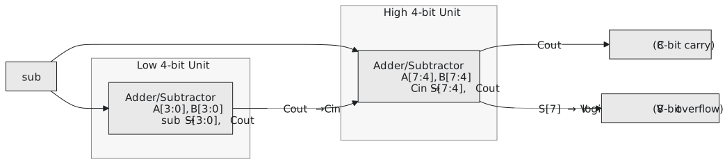
The 8-bit flags come from the high unit: Z is the NOR of all eight result bits, N is bit 7, C is the carry out of bit 7, and V compares the carry into bit 7 with the carry out of it. The carry between the two units is an ordinary internal carry, not an overflow.
This is how processors do arithmetic wider than their ALU. The add-with-carry instruction feeds the carry flag from one addition into the carry-in of the next, and two of them add 64-bit numbers on a 32-bit machine.
The ARM Cortex-M0 ALU is, in structure, this circuit at 32 bits, with exactly these four flags going into the program status register, and every conditional branch in Thumb code reads them.
Timing
| Path | Delay |
|---|---|
| sub or B through the XOR layer | 1 |
| carry chain through FA0 to FA3 | 8 |
| N and C flags | 0, wires |
| V flag, one XOR after $c_4$ | 1 |
| top sum bit, then the Z NOR tree | 1 + 2 |
| worst case, Z | about 12 |
The zero flag is the slowest output because its NOR tree waits for the last sum bit. If Z is on the critical path in a real design, it can be computed speculatively from partial results in parallel with the final adder stage, and synthesis tools do this automatically at high effort levels.
Practice Exercise
Problem 1. Compute $A = 1001$, $B = 0110$ with sub = 0. Give the four flags and interpret the result as signed and as unsigned.
Solution
X = 0110, carry-in 0.
| Bit | A | X | Cin | Sum | Cout |
|---|---|---|---|---|---|
| 0 | 1 | 0 | 0 | 1 | 0 |
| 1 | 0 | 1 | 0 | 1 | 0 |
| 2 | 0 | 1 | 0 | 1 | 0 |
| 3 | 1 | 0 | 0 | 1 | 0 |
$S = 1111$, $c_3 = 0$, $c_4 = 0$. Z = 0, N = 1, C = 0, V = 0.
Signed: $-7 + 6 = -1 = 1111$. Correct, no overflow. Unsigned: $9 + 6 = 15 = 1111$. Correct, no carry.
Problem 2. For two chained 4-bit units forming an 8-bit unit, where do the 8-bit carry and overflow flags come from?
Solution
The low unit’s carry out goes to the high unit’s carry in, and sub goes to both. The 8-bit C is the carry out of the high unit (bit 7). The 8-bit V is the XOR of the carry into bit 7 and the carry out of bit 7, the same construction as the 4-bit case at the new top bit. The carry between the units is not an overflow; it is an intermediate carry that has to propagate.
Arithmetic is only part of what a processor’s ALU does. The next article steps back and asks what an ALU is, which operations belong in it, and why every one is built the same way.