The Barrel Shifter
In the last article, shifts by a constant were free. This article is about what happens when the shift amount is a value in a register, known only at run time. Wires cannot rearrange themselves, so we need logic. The obvious approach, a chain of $N - 1$ shift-by-one stages of which the right number are enabled, works but has a delay that depends on the shift amount, which is a nuisance for timing analysis. The barrel shifter does better: it shifts by any amount in the same fixed number of stages, and that number grows with the logarithm of the width.
The idea
Any shift amount from 0 to $N - 1$ is a sum of distinct powers of two, which is just its binary representation. A $k$-bit shift amount $s$ is
$$s = s_{k-1} 2^{k-1} + \cdots + s_1 \cdot 2 + s_0 \cdot 1$$
So a shift by $s$ is: shift by 1 if $s_0$ is set, then by 2 if $s_1$ is set, then by 4 if $s_2$ is set, and so on. Each of those is a constant shift, which is free, wrapped in a row of 2-to-1 muxes that choose between “shifted” and “not shifted”. A barrel shifter is $k = \log_2 N$ such rows in series, each controlled by one bit of the shift amount.
An 8-bit right shifter
Three stages, controlled by $s_2 s_1 s_0$ (Figure 1).
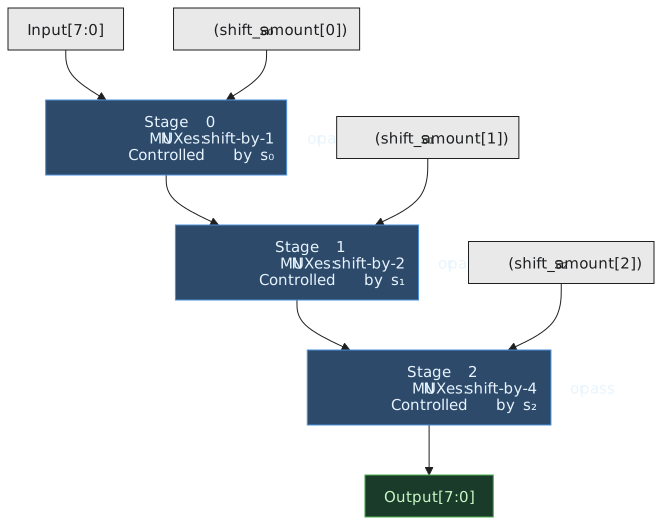
In stage 0 the mux at output bit $i$ chooses between input bit $i$ (no shift) and input bit $i + 1$ (shift by one), with a 0 for the top position. Stage 1 does the same with an offset of two, stage 2 with an offset of four. Inside each stage the wiring is a constant shift; the muxes are the only gates.
Tracing 10110100 shifted right by 5
The input is 180. The amount is $5 = 101_2$, so $s_2 = 1$, $s_1 = 0$, $s_0 = 1$. We expect $180 / 32 = 5$, that is $00000101$.
Stage 0, $s_0 = 1$, shift by one: $10110100 \to 01011010$.
Stage 1, $s_1 = 0$, pass through: $01011010$.
Stage 2, $s_2 = 1$, shift by four: $01011010 \to 00000101$.
Result 5. The total shift was $1 + 4$. Stage 1 did nothing, but the data still went through its muxes, so every path was three mux delays long. A shift amount of zero works the same way: every stage passes through, and no special case is needed.
Whether the small stages come first or last does not change the result, since the shifts add up either way, but the intermediate values differ, and when you debug one it helps to know which order was used.
Timing and area
Each stage is one mux delay, so the whole shifter is $\log_2 N$ mux delays regardless of the amount:
| Width | Stages | Muxes | Area, roughly |
|---|---|---|---|
| 8 | 3 | 24 | 72 gate equivalents |
| 16 | 4 | 64 | 192 |
| 32 | 5 | 160 | 480 |
| 64 | 6 | 384 | 1152 |
A 32-bit barrel shifter is about the size of a 32-bit ripple-carry adder and shifts by anything in five mux delays. Doubling the width adds one stage.
Arithmetic shift
A logical shifter fills the vacated top bits with 0. For an arithmetic right shift the fill must be the sign bit of the original input. The change is small: instead of grounding the fill inputs of each stage’s top muxes, connect them to input bit $N - 1$, gated by a mode signal:
$$\text{fill} = \text{arith} \cdot \text{in}[N-1]$$
Because the sign bit never changes under an arithmetic shift, the original sign bit is correct as the fill at every stage. That is $N - 1$ AND gates across all the stages, negligible next to the muxes.
Both directions
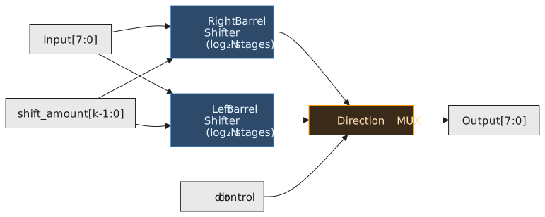
A direction input makes one shifter serve for left and right. One way is to reverse the input bits, shift right, and reverse the output bits; reversals are free wiring, so this costs two mux rows at most. Another is to build both offsets into each stage’s muxes. Synthesis tools pick whichever is smaller for the target (Figure 2).
The funnel shifter
A more general form takes two $N$-bit inputs $A$ and $B$, concatenates them into $2N$ bits, and extracts an $N$-bit window starting at any offset:
$$\text{out}[N-1:0] = {A, B}[\text{offset} + N - 1 : \text{offset}]$$
The same mux tree does it. Funnel shifters are used in floating-point adders to align the smaller mantissa while keeping its guard bits, in the load path of a processor to extract an unaligned word from two adjacent memory words, and in string-copy hardware to deal with byte offsets.
Where you meet them
Every processor has one. ARM’s is unusual in that it sits in front of the ALU, so ADD R0, R1, R2, LSL #3 shifts and adds in one instruction. A floating-point adder has at least two, for alignment before the add and normalisation after it. Cipher and hash hardware use them for rotates with the fill wired to the outgoing bits. On a Cortex-M4, a shift instruction takes one cycle, and fixed-point DSP code leans on that: after multiplying two Q15 values, >> 15 rescales the product in a single barrel shift.
On an FPGA, a 4-input LUT can implement a 4-to-1 mux, which is two barrel-shifter stages, so the synthesizer folds stages together and the real LUT depth is less than $\log_2 N$. As always, the timing report on the actual device is what counts.
Practice Exercise
Problem 1. Design a 4-bit right barrel shifter with a 2-bit shift amount, then trace $1101$ shifted right by 3.
Solution
Two stages. Stage 0 ($s_0$): output bit $i$ chooses between in[$i$] and in[$i + 1$], with 0 at the top. Stage 1 ($s_1$): output bit $i$ chooses between the stage-0 output at $i$ and at $i + 2$, with 0 at the top two positions.
Shift by 3 means $s_1 = 1$, $s_0 = 1$. Stage 0: $1101 \to 0110$. Stage 1: $0110 \to 0001$. Result 1, and $13 \gg 3 = 1$.
Problem 2. A 32-bit barrel shifter has five stages of 150 ps each. What clock rate could it support on its own?
Solution
$5 \times 150 = 750$ ps, so about 1.33 GHz if nothing else were in the path. Allowing 150 ps of setup and perhaps 300 ps of routing gives 1.2 ns, about 830 MHz. In a 28 nm process the mux delays are shorter than 150 ps and such shifters close timing at 1 GHz.
Problem 3. How is the 8-bit right shifter modified for arithmetic shift?
Solution
The fill inputs, one in stage 0, two in stage 1 and four in stage 2, are connected to in[7] AND arith instead of to ground. Seven AND gates. The original sign bit is used at every stage, since an arithmetic shift never changes the sign.
That completes the multipliers and shifters. Section 2.4 leaves arithmetic and looks at something that affects every combinational circuit in this module: the glitches, called hazards, that appear when signals arrive at a gate at different times.